Received these questions via email because user was unable to use forum. Prefer to answer here so others can benefit from the effort I put into answering these questions. Response in next post.
What are the wire lengths of the CT’s? If less than 24”, is there any problem with splicing in additional cable and if not, can you identify the cable used? I expect the cable lengths I will need for some of the circuits in the panelboard to be as long as 7 feet or so. Perhaps, I should consider a different CT than those packaged with your North American kit?
Will I be able to plug 2 VT transformers into a standard duplex receptacle (which I will split between 2 phases)? If not, I could use a shorty extension cord. I intend to utilize direct reference voltage from each phase and this would use 2 of the available 14 monitoring spaces from the iotawatt.
My project involves submetering several circuits from a main, 3 phase, 600 amp, 120-208V panelboard. The panel board is feed by parallel conductors (2) for each phase. I want to monitor each phase. In reading through the docs.iotawatt, I believe I can place a 100 amp ct on each parallel conductor and combine the 2 CT’s from each phase with a phono jack coupler for insertion into one of the monitoring inputs. Is this correct? Would I need to double the values from the 2 combined CT’s? This mains monitoring would use 3 of the 12 available iotawatt monitoring spaces.
The other circuits I need to aggregate for submetering are:
1- 3 phase, 100 amp circuit for a lift (balanced load) which I intend to use 1- 100 amp CT for monitoring that would use 1 of the 9 available iotawatt monitoring spaces.
1 - split, (2 phase) 100 amp, 208 volt circuit for a car charging sub panel – all loads at 208 v – balanced which I intend to use 1- 100 amp CT for monitoring would use 1 of the 8 available iotawatt monitoring spaces.
1- split phase, 100 amp, 120-208 volt circuit for a sub panel for various loads which are unbalanced. I intend to use 2- 100 amp CT’s for monitoring would use 2 of the 7 available iotawatt monitoring spaces.
1- spare sub panel circuit that would be a duplicate of c above. Do not expect to purchase or install the CT’s for this future panel at this time, but I am allocating 2 CT’s for monitoring that would use 2 of the 5 available iotawatt monitoring spaces.
Not a problem, however the 120V kit does require you select at least two mains CTs. You can use the Generic kit if providing alternate CTs.
Yes, they are sideways so two will fit.
Not really. Conventionally, when you say “3 phase, 600 amp”, that would mean that each phase has a 600A capacity. That is also supported by your description of parallel cables for each phase. So, using 100A CTs is definitely not appropriate, and I doubt the 16mm 100A CTs would fit around the cables anyway.
In this situation, for each phase, you could use
2x400A into 2 IoTaWatt inputs.
2x600A combined with a splitter into 1 IoTaWatt input.
2x400A combined with a splitter into 1 IoTaWatt input changing IoTaWatt burden resistor to 10 Ohm.
1x600A with both cables running through it into one IoTaWatt input. The CT is 36mm opening so your incoming cable would need to be 18mm or less.
1x600A Echun ECS55600 (special order 3-4 weeks) into one IoTaWatt input.
OK
Two ways to do that:
2x100A CTs into two inputs with direct reference on each.
1x100A CT into one input with derived reference. (You can still use direct reference for 120V circuits)
This is technically not a split-phase subpanel. It uses the same physical panel, but the phase of the 208V is not the same as the 120V phases. You have three different phases at play. That said, what you describe will monitor the sub-panel correctly.
Our project has progressed, and we have installed all equip purchased via iotawatt store inclusive of 2x600A CT’s on each of the 3 pairs of parallel main feed conductors for our 120/208 V 600 amp panel & 3 VT’s at each phase leg. We have set up the iotawatt for direct reference and used the phono plug couplers for each of the 2 CT’s on each of the phase legs.- Just want to confirm, since we used the couplers, we do not need to double the input value?
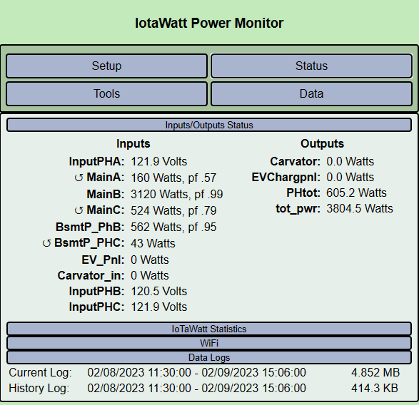
The status display of the iotawatt indicates 2 of the phase CT’s are set in reverse. We have confirmed they are not. All of these CT’s are set the same.
Do you have any suggestion on what we can investigate to see why this is so?
As mentioned in original post, we have a balanced 3 phase, 100 A load for which we have placed 1 100A CT on one phase leg. When we configure the output for this, should we multiply by 3? by 1.723?
We have configured this CT in reference to the source phase VT.
We also have a 2 phase, 100A, 208 volt balanced (no 120 load) car charging panel which we have placed 1-100A CT. When we configure the output for this, should we multiply by 1.723? We have configured this CT in reference to the source phase VT.
We also have 120/208 volt subpanel for which we have placed 2- 100A CT’s on the feeds each configured with the appropriate source phase VT. When we configure the output for this pan el, do we just multiply the kw output by 2?
Lastly, the readings we are getting appear to show that 1 phase has almost 100% more load than the other 2 (it is the one that does not have the reversed CT swirled arrow). This does not seem correct since most of the loads in this panel are balanced 3 phase loads. Any thoughts on this?
My first impression is that the voltage reference for A and C are reversed. That is most likely the problem, but it could be more complicated if strict polarity and CT orientation were not observed.
To test this, I would suggest that you simply swap the VT inputs for channels 0 (9V AC REF) and channel 14.
x3
x 1.723
No, you would add the two.
First item should fix that.
EDIT:
Not quite sure. Usually use derived reference for phase-phase loads. You can use derived for this circuit and leave everything else direct:
Check allow derived reference in the inputs setup.
For that 100A CT select phase = A_B.
If that does not produce a good result check phase C-A.
Big thanks for your prompt responses to date. Very helpful and we are very impressed with the IoTaWatt’s performance.
With respect to our query on the reverse status of 2 of our phase legs (A & C) , and your response suggesting the reference VT’s were reversed, turns out that was partially true- We determined the VT’s for A & C were monitoring the correct phase leg, BUT we were not aware the polarity of the VT’s impacted the readings. Once we turned them around in the plug, the reverse status disappeared. I don’t recall seeing info in your documentation relative to the proper polarity of the VT’s, but perhaps a cautionary note should be added.
Withe respect to the apparent imbalance in our phases in our panelboard, we just moved a couple of breakers to balance and we are pretty good now. Have not yet had any cars using the charging circuit yet though, so we made need to rebalance again.
Found an odd thing in Graph+, when one selects the 2 day or 3 day look back, the x axis remains at the same 24 hour display as today, instead of 48 or 96 hours. Data is correct however.
Please ignore my comment on Graph+. Somehow thought the lookback was meant to include all 2 or 3 past days inclusive of the intervening days, not the discreet days.
My Caveat. Switching the VTs resolved the incorrect Watts and PF. Reversing the VT would eliminate the “reverse” sign but that’s just informative, IoTaWatt would have been correcting it by reversing the sign.