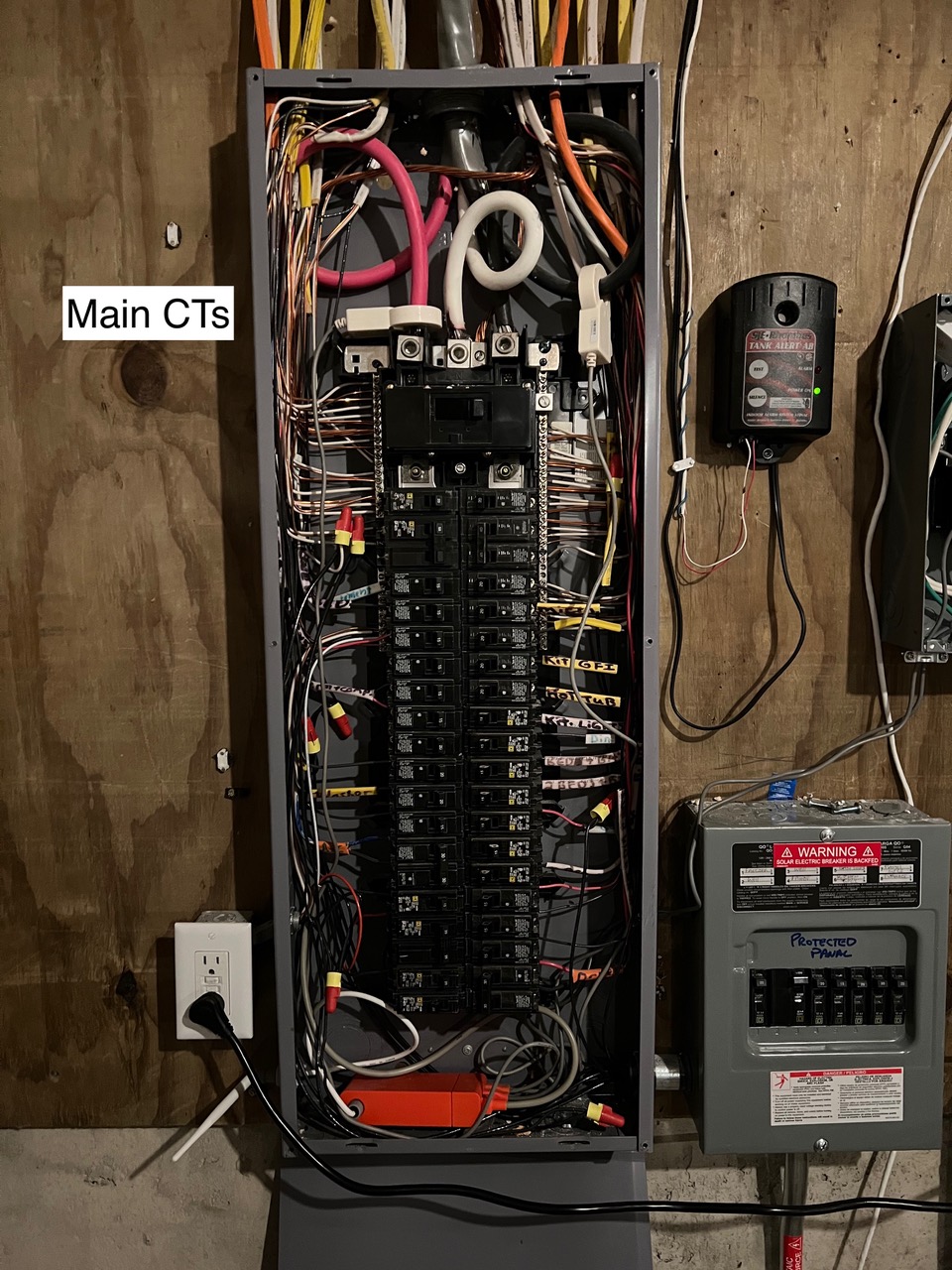
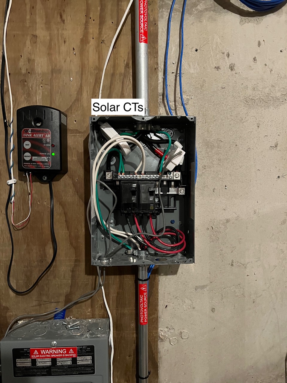
Based on other topics I’ve seen here, I think IoTaWatt will work for my system, but I wanted to share my schematics to make sure. I’ve also shared some pics of where the CTs are for the sense currently (one pair for grid, one for solar). I think I basically need 3 sets, minimum, to catch what’s going on with the protected panel load? Maybe I need one for each inverter? The system is Generac PWRcell based (battery/inverters/pv links/etc.)
If I understand your requirement, it is to be able to see the activity on the critical panel, which appears to be able to switch to battery in the event of grid failure. Pretty straightforward.
Like the Sense, you would put two CTs on the incoming grid Mains. Behind that, you have a few options:
You can monitor the total solar output as with the sense by placing a pair of 100A CTs in the solar sub-panel, and add a pair of 50A CTs to the critical panel feed. As I understand it, the total solar production is the sum of the critical panel load and the solar sub-panel import/export (signed value). From those basic metrics you can create IoTaWatt outputs (calculated values) that represent:
Grid import/export
Total Solar Production
Critical Panel Usage
Non-critrical loads usage
Direct solar usage
Another option would be to place a pair of 50A CTs on the output of each inverter rather than the 100A on the solar sub-panel. This would add visibility to the output of each inverter. The total solar output would then be calculated by adding the two feeds together with an IoTaWatt output.
If it were my setup, I’d go with measuring the inverters independently. There is enough wire in the sub-panel to measure each with a single 100A CT rather than two 50A (wires are passed through in opposite directions). Depending on the options chosen, you will use between 6 and 8 IoTaWatt inputs for the above functionality. That would leave between 6 and 8 additional inputs that can be used to measure other specific loads.
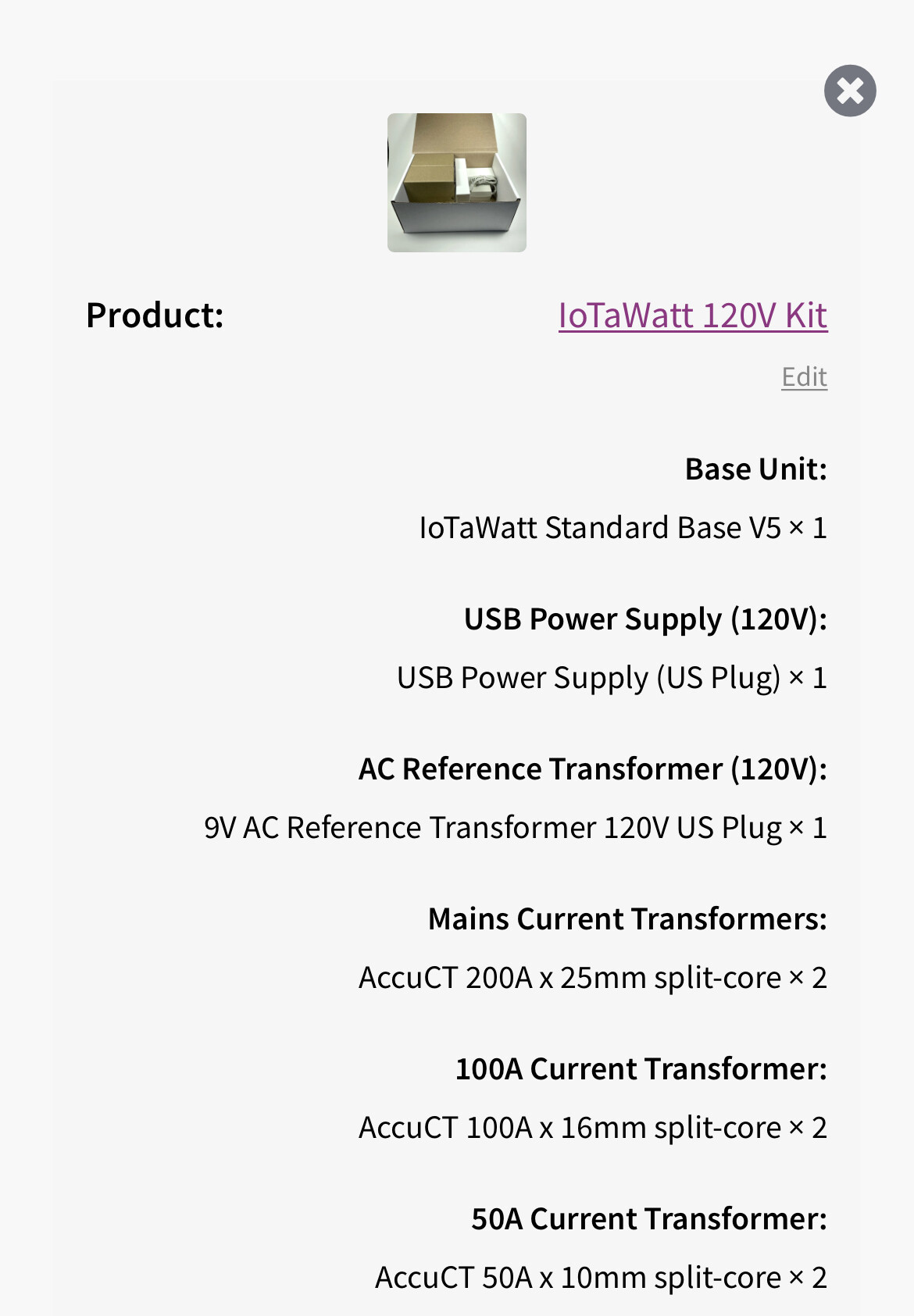
The voltage reference and USB power supply would be connected to the critical panel, assuming it is grid connected when the grid is up.
I think this would do me to start? I’m a little unclear on your comment about using a single 100A for the solar panel, so maybe I only need one of those?
That will work. It’s one 100A for each inverter (or two 50A). See the docs here for an explanation of passing both conductors through the CT in opposite directions.