Share with group my New US Install

Looks good.

I’m not following you on the Barn/Garage thing. Are you saying that the Barn is a 100A CT? I thought the problem was that you couldn’t get the loop in that fat cable to the Barn.

I think that freezer has a heater around the door to prevent sweating in humid conditions. I bet the 143 watts is more than the compressor uses. That’s one of the reasons chests are more efficient, but they are a PIA to access.

Be good to get a handle on that “Other” usage. If you have inputs left, you can put a CT around multiple circuits to get better coverage. Just make sure to run one leg in one direction, and the other leg in the other direction. The CBs alternate legs as they run down the panel.

If you could log the Mains usage for awhile and post the comparison to the meter, that would be helpful to reinforce the accuracy possible.

Thanks

Will do on the monitoring part.

The Barn (100A) and Garage (50A) cables are too large for two in the one CT. The other you sent is a 50A, so I attached that to the other leg of the Garage so I have the two 50A CTs going to the splitter and into the unit. Not sure of the barn cable size, but it is just big enough to fit the one 100A CT around it; so for that one I’m only monitoring one leg and just doubling it. Right now that is not as big of a deal until we get our heated water buckets up and running. That is when I may be looking for a second 100A CT and another splitter.

I intend to use #13 and #14 ports for the two Solar feeds once installed as I think it will be an easier install like the mains. So that give me one lest #12 open for some other specific items such as kitchen receptacles (Microwave and toaster oven) which are very big loads as you can imagine. I wanted to get the mains back up and things working as expected before making more changes. :slight_smile:

Here is a picture of the barn cable doing its twist in the panel.

IMG_5520

@quella, great looking install! I am planning something similar in the USA. Questions:

My panel area is similar to yours, but I have a large sub-panel right beside the main panel. I want CTs in both. Is there a legal or accepted way to feed the CT wires between the panels? Conduit of some kind would be nice, but the knockouts don’t line up (of course!) and they are only 2" apart so limited working space. Flex tube? I’d place the plastic junction box to the right of main panel, sub panel is left of main, so sub panel CTs would feed through main, through dogleg, to junction box and iotawatt.

I see several “junction boxes” or “project boxes” available. What did you use exactly? Not sure if any plastic box is OK, or should be UL listed, or if screw cover is needed or if latched, hinged cover is OK. Most seem to be sealed, waterproof, for outside use, which is OK but I don’t really need for this.

What are the dimensions of the iotawatt? I could not find that info on the web sites. Looks like about 4" x 5" x 1.5"? Just want to make sure the box I get will fit the iotawatt and CT and power cables and connectors. @overeasy, maybe add the dimensions to the catalog page?

Thanks
John

@jfree23, sounds like you have some planning to do like I did. At first I was looking to install the unit below the panel out of the way of connections and to provide me a way of simply running the cables down (via gravity) and out the panel to the junction box. Well that plan was not feasible when I took a look at my physic setup and had to change my plans. Most of my connections came in from the bottom and top, so I needed to find a way to go in from the side. There were no places where a punch-out hole, or one that was 1" lined up with the expected box placement. So, I decided to purchase a step-drill bit and I cut a hole in the side of my panel for the 1" conduit. I would recommend an electrician if you are not comfortable working with high-voltage as they will also have the better option of using a punch cutter; which is a cleaner way of doing cuts into a box.

Without seeing your configuration, I would assume you could run conduit from the sides or if not like mine, the bottom and have them both terminate into a single box with two feeds; one to each panel. The step drill bit also gave me the ability to cur the proper hole in the plastic box for my 1" conduit. Ah, it seems like you will need to transition through the main panel from the sub to the IoTaWatt box… Based on the length of run, I would not see an issues with the cables that Overeasy (Bob) sells as they come with 1.5m of cable unlike the ones you get on Ebay that have 1m cables. Those may be too short.

I purchased one outdoor style electrical box at first that had a door which closed and I could remove all the innards to make an empty cavity for the IoTaWatt, but this box ended up being too small for the unit and the cables plugged in, they take up more space than I would thing. The images that I had included showed a 8"x8"x4" ( I thought it was 9x9), but it looks like this one: https://www.amazon.com/Carlon-GID-663193-E989N-Box-Junction/dp/B0037MZW1A If you have the time and want to do it right, I would recommend a NEMA type box with a door and the ability to lock it or secure it if you want. I found mine at Lowes here in the US and they had the bigger one in stock for about $16.00. I know Home Depot also caries them.

From the image of the box I have, you can see that I do not have much room up or down with the cables installed, but I do have room in the depth side. The two cable connections take up space that if you are not expecting it may surprise you. That is why the first box I purchased seemed big enough but it was not.

Happy to answer other questions if you have them. I have been though it once and willing to help others like others helped me.

Yep, planning and working through initial issues now. In pic, sub panel on left, main on right, plenty of space to right of main where I hope to put iotawatt. Lots of other stuff below sub. Could move some of it fairly easily and put iotawatt box there if needed. I have to open up panels and see where the wires really run for CT attachment, plan the CT runs, see if 1.5m cable really enough.

I’m generally ok working on a live panel, not so OK with drilling or punching holes! Like to avoid that by using knockouts on right side of main. May consult electrician but that could double/triple cost of project easy. Maybe town wiring inspector, as I’m not clear on exactly how the CT wires need to be protected at a minimum. Personally I’m not concerned about just running them through knockout holes, maybe with bushings or grommets, no conduit, just bundle them, tie them, maybe sleeve them, but I’d like it to be legal, or at least not TOO illegal.

If I put the iotawatt where the Hunter sprinkler control is now, it is closer to both panels, but means moving other stuff, and still messing with conduit to get a conduit run from each panel to that spot. IF conduit is really needed - kind of hoping some kind of flexible sleeve could be acceptable.

Ah, I wondered if your box was really 9 x 9, all I could find was 8 x 8, glad you confirmed. That is outside dimension too. Looks like ideally we’d have 8 x 8 inside minimum, but could be 2.5-3" depth… I was looking at boxes like this

but was not sure if they are OK for this use, UL listed or whatever. Will check Lowes also.

Thanks for the info and offer to help!

John

1 Like

John,

My box from Lowes look like this (https://www.lowes.com/pd/CARLON-8-x-8-x-4-Junction-Box/3260229) and as you can see from the description it is 8x8x4 internal and there is some space to spare with the unit mounted. For some reason the one they show says non “longer available” and the one in the image has 4 screws where mine has 8 (3 top, 3 bottom, and one each side). Mine also does not have the small feet, is is just a box shape. I like the second option from Amazon you show, as that has a door and closure. You will be making modification or slight tweaks so I left mine open (due to screws) until all was done. If you have the time and can spend a bit more, I would go with the Amazon second one if I had to do it again.

I agree that the best location for your IoTaWatt box is where the timer box is currently placed. If you are able to move it and put a box there I think you would have a winner. Electricians are only thinking of themselves when they install these panels :). I would use something like 1.5" conduit based on the number of runs you expect, or 1" if you plan on distributing them between panels. Mine is 1" and it is tight with 12 CT cables but I plan on snaking through the others in the near future.

If there are 1" punchouts at the bottom of the panels, that would give you the most room for the drops. Just not sure what you have below. The sub seems to have bottom punches it was done during install. I think it would be difficult to use the main as a pass-through in this configuration. It may be good for an electrician to do the conduit work if you have to do any drilling as you said. I know there is a cost, but this is your house you are speaking about.

1 Like

It has been a while, and I’m not “done” yet (ha ha, maybe we never are), but its all installed and working pretty well. Some of you might be interested to see this - USA split phase 240V setup. Still somewhat of a tangle of CT wires, splitters,etc. There are 22 CTs in there, combined via splitters, a couple left for summer/winter changeover (AC compressors in summer, roof snow melt in winter), some where multiple circuits go through 1 CT, some doubled on one leg of 240V circuit.

I chose not to enclose the CT wires in conduit; just no way to make that all work, and couldn’t really see the point. I may try to cover with smurf tubing or similar, later. I just ran them through panel knockouts in plastic cable clamps, with the clamp cut out and smoothed inside. Tied them all neatly inside the panel, then looped outside.

The Extreme Broadband enclosure shown in the thread above worked pretty well. The iotawatt mounting clip screwed nicely to the tracks inside, so iotawatt can easily be unclipped and pulled partly out for access, then clipped back. The many cable slots with foam retainers were great to keep the cables under control, and still easily moveable. Not tons of extra room inside once I started with the 2, 3, and 4 way splitters! But it all fits. Door has a clip, and a lock option - I don’t need to lock mine.

Thanks to so many in the community for good ideas posted along the way, and especially to Bob for the great product and all the ongoing hard work on continued support and tips and hints!


John

1 Like

Awesome to see and know that you are up and running. And, yes, we are never done. There are always little tweaks and tunes as you said; and season changes help that also.

Wow, I though I had quite a bit with mine, but with your sub panel, etc, it looks very nice. You can always clean up those CT wires another day; or not. :slight_smile:

I would have gone the conduit route myself for the CT wires, but that is more for form than function. Again, you can clean them up later of you desire. I like the run between the sub-panel and the main panel for the CTs. It looks professional and clean. Good job!

I agree that it looks quite nice and I like that you have the option with a latch and lock if ever needed. When it is all closed up, it gives you access to the box quickly of you should need. The junction box I used in my install requires eight screws to come off. However, once all is working, I do not plan on taking it out.

Thanks can not be said enough for this group and Bob for all the help, direction, pointers, and feedback. I’m sure Bob does not sleep ever as he is aways on the board answering questions and willing to assist at any time. Very nice install, thanks for sharing it.

Thank you for taking the time to share your install photos and links to some of the accessories you used. I have been contemplating how to install my IoTaWatt for a month now. :slight_smile: I have two panels as well, however one is on the outside of the house (Main Panel with all 220VAC breakers) and the other is in my garage (Sub Panel, mostly 110VAC breakers). Unfortunately, my two panels are about 60 feet apart from one another, so it may be simpler to just buy another IoTaWatt, since I need significantly more than 14 CTs anyway.

My garage mounted panel is flush-mounted in the sheet-rock, so I am going to need to perform some cutting and add some conduit.

Again, thanks for the write-up and the pictures. Seeing your installation helps me to visualize mine.

I have to say that’s a pretty amazing instrumentation effort. It may look easy to anyone whose not tried it, but getting that number of CTs in a panel as neatly as that is very hard to do. It would not be possible with YHDC SCT013-000 CTs as they are much larger and the cables are too short.

But enough about the visuals. How is the data working out?

Great to see some interest in this! I’ll try to answer; let me know if there is or should be a better thread for these topics.

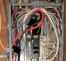
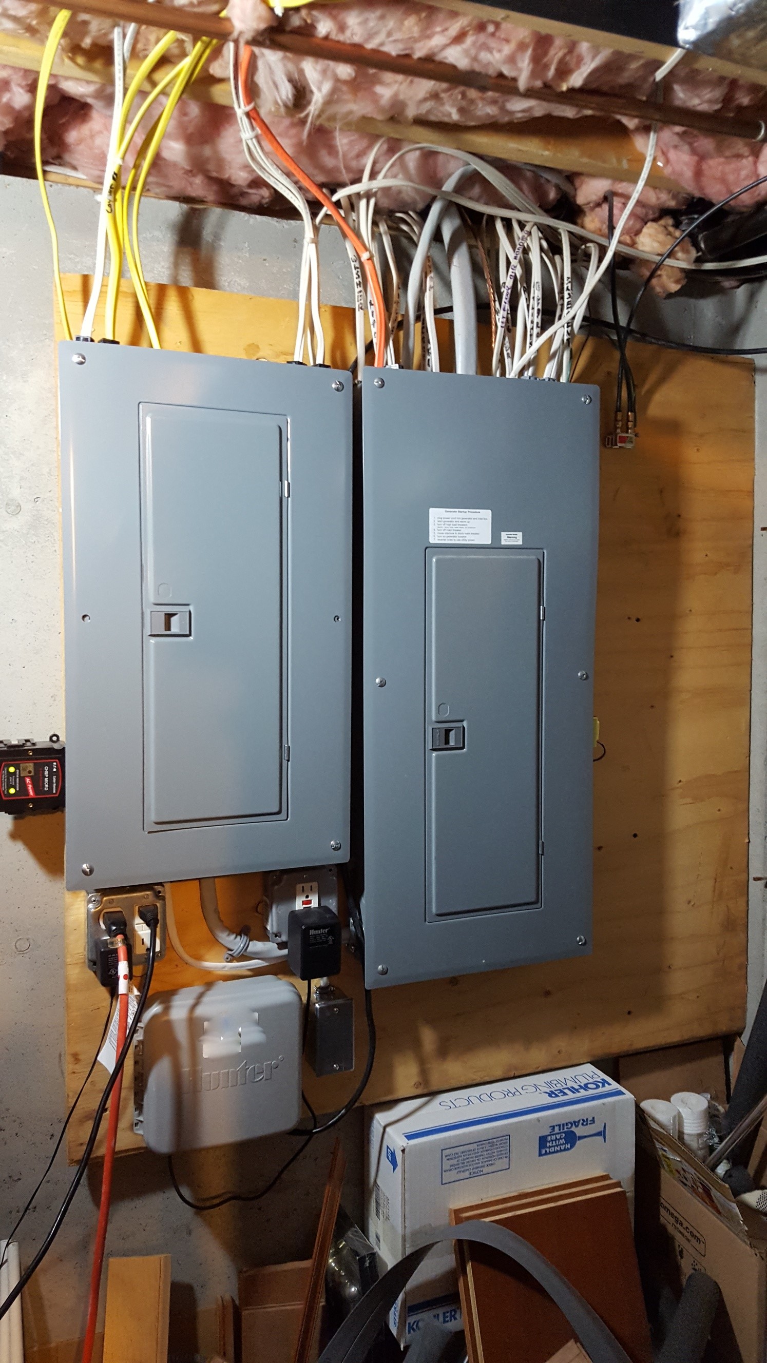
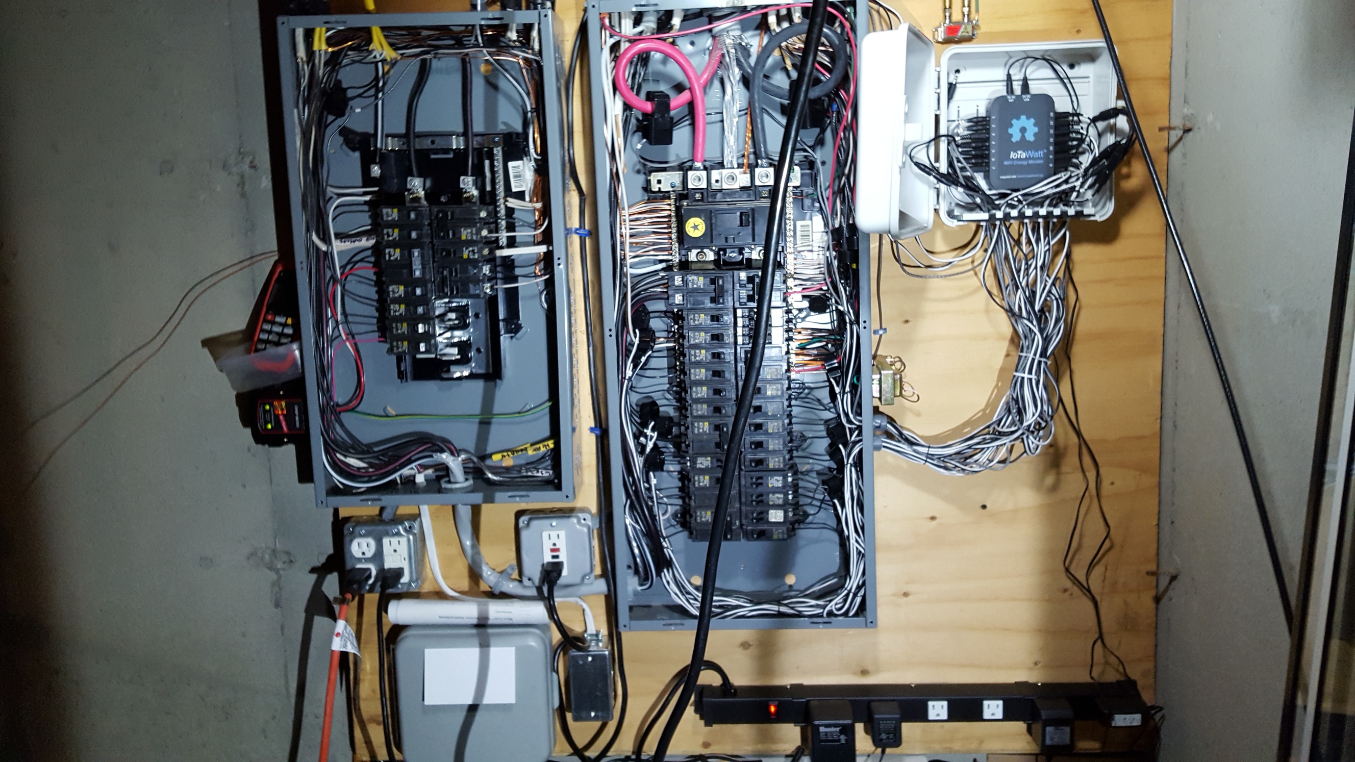
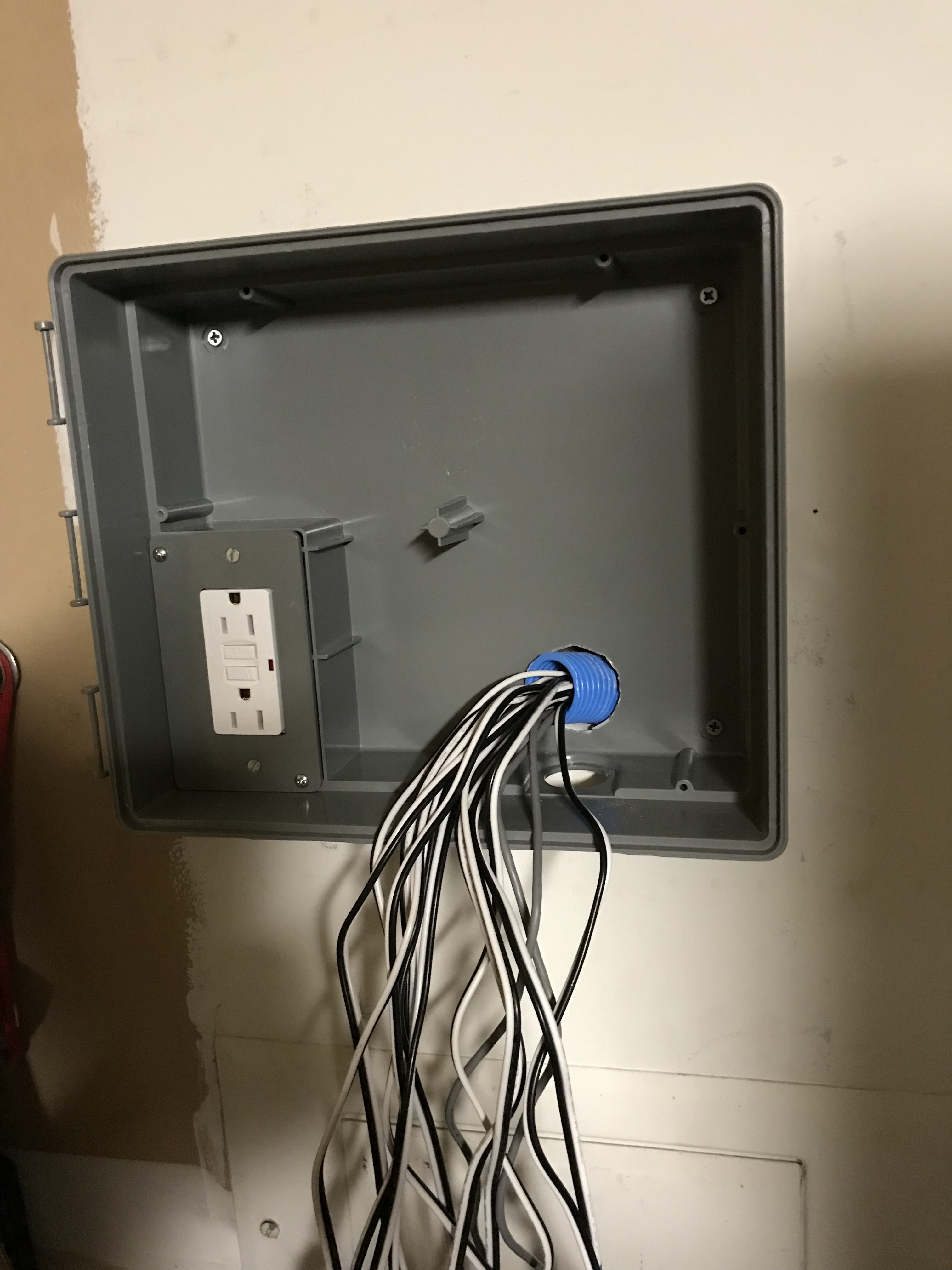
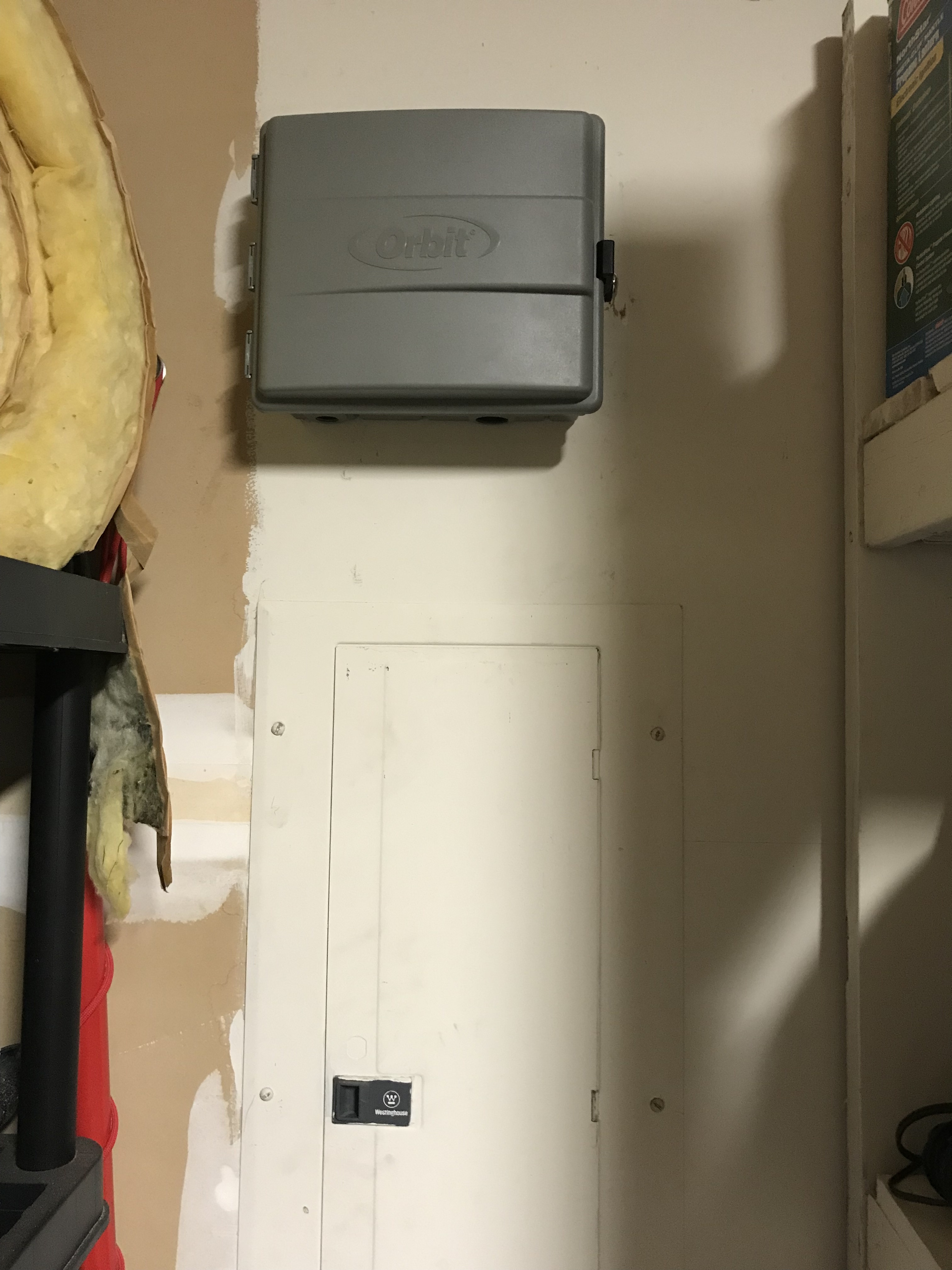
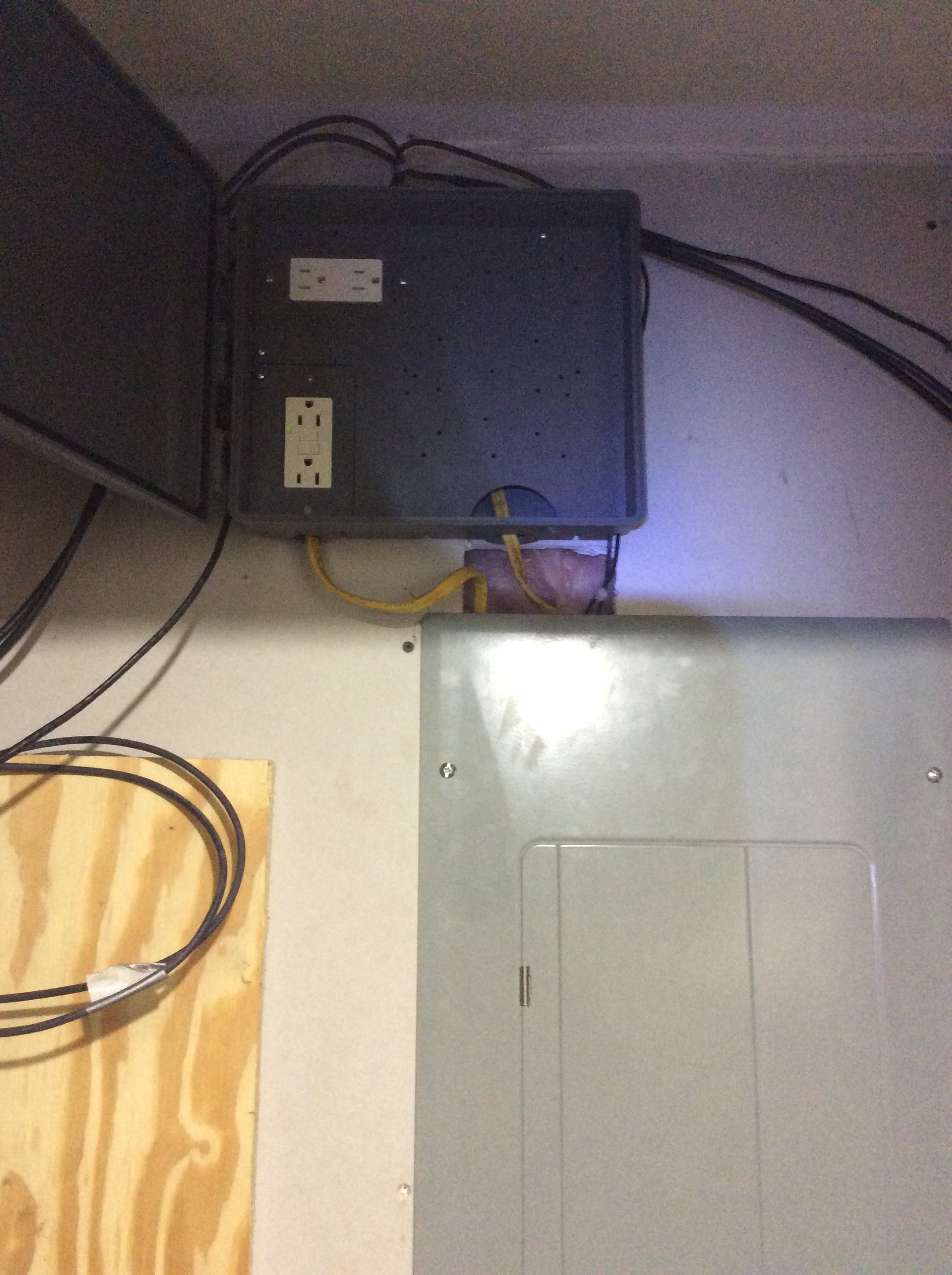
@quella: there is no CT run from sub to main panel. There is one place it almost looks like that, but only the subpanel power feed from main goes between. The CT runs exit the subpanel at top, run across the top of the main, behind the vertical HV wiring, then down between main and iotawatt box to enter in bottom. Any other way, CT wires were too short. All the larger knockouts in panels I’d use for conduit resulted in CT wires too short, or too much interference.

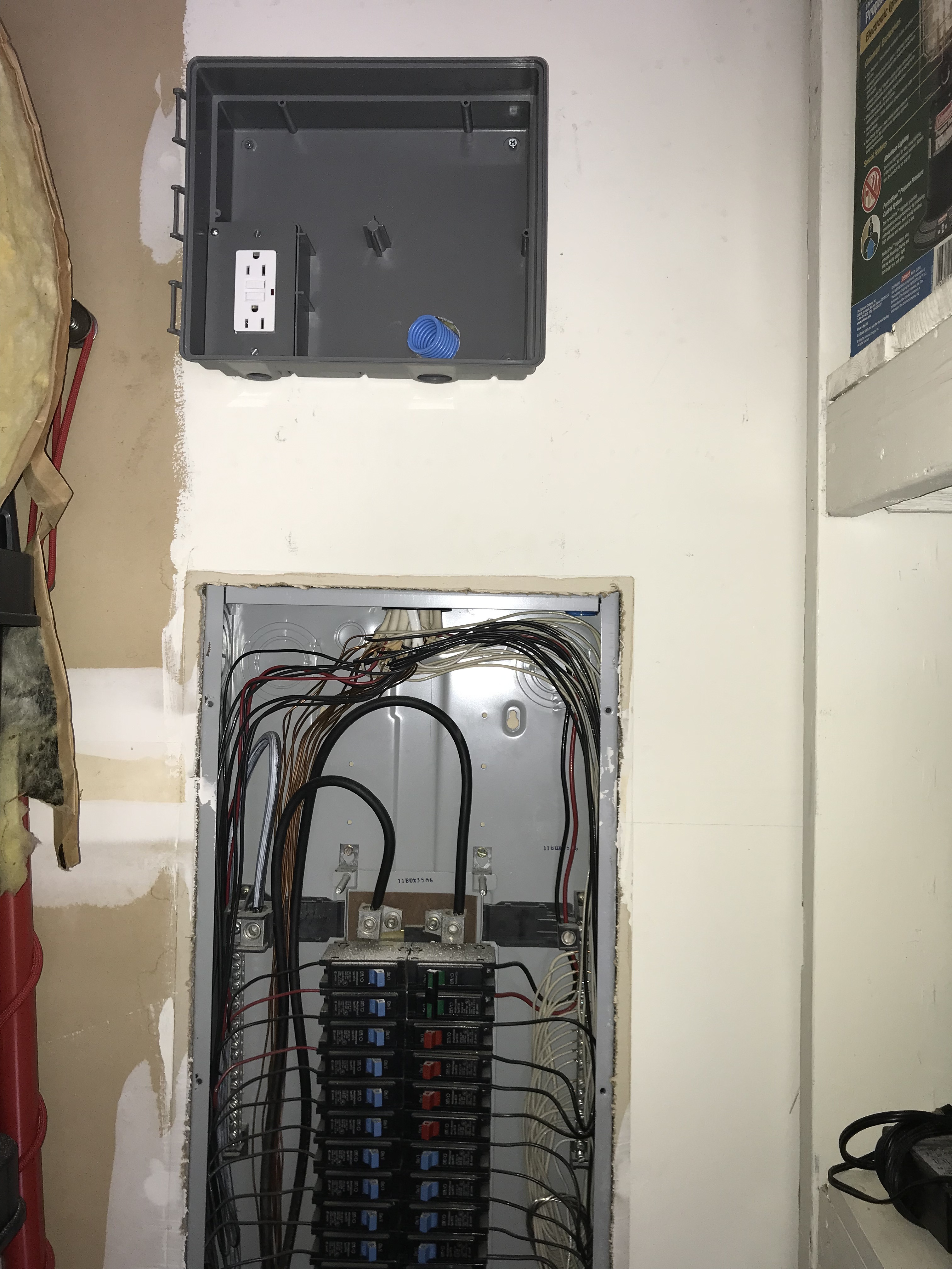
@ogiewon: you will probably need 2 iotawatts, and have to open up your drywall but you may also want to consider using low voltage wiring techniques, smurf tubes and such. Easy for me as my area is open and can stay that way and I’m more concerned about being safe and reasonable than trying to meet current code. Just don’t think that you will need 1 iotawatt channel per CT or per circuit. (see below)

@overeasy: The data is great, and is coming together in a way that makes sense to me in my situation. Has taken quite a while to work out, connect and map things, look at what I’m tracking, create outputs, then rethink and redo things, move CTs, group different ways. I don’t know if there is a generic method, “how to approach it” FAQ or something like that. I started out like @ogiewon sounds - get iotawatt US kit and set of CTs, hook up bunch of circuits 1 to 1, targeting heavy consumers, with panels open, CT cables dangling, run it, see how it looks in real time. Did not think much in advance about exactly what I WANTED to see, I’d recommend doing that though :slight_smile:

My environment - single house, not all-electric, no solar, using 25-30 kWh/day. (500-700W at night). Complex HVAC with 3 zones, separate circuits for AC compressors, air handlers, oil fired boiler (also heats hot water), ductless mini-split - already 8 to monitor! And also electric range, washer, dryer, dishwasher, refrigerator, microwave, espresso machine, 3-4 areas with PCs, TVs, etc, some use 2 or more circuits. Also 2 circuits for ice melting roof heat wires. Many small devices everywhere that have constant small draw.

Easy to assign the mains, with a 200A CT on each phase, and an output to sum them, but then what? Just looking at the heavy users and all the HVAC units is interesting, but only covers a small % of the total kWh as they only run occasionally, and already consume all the iotawatt channels.

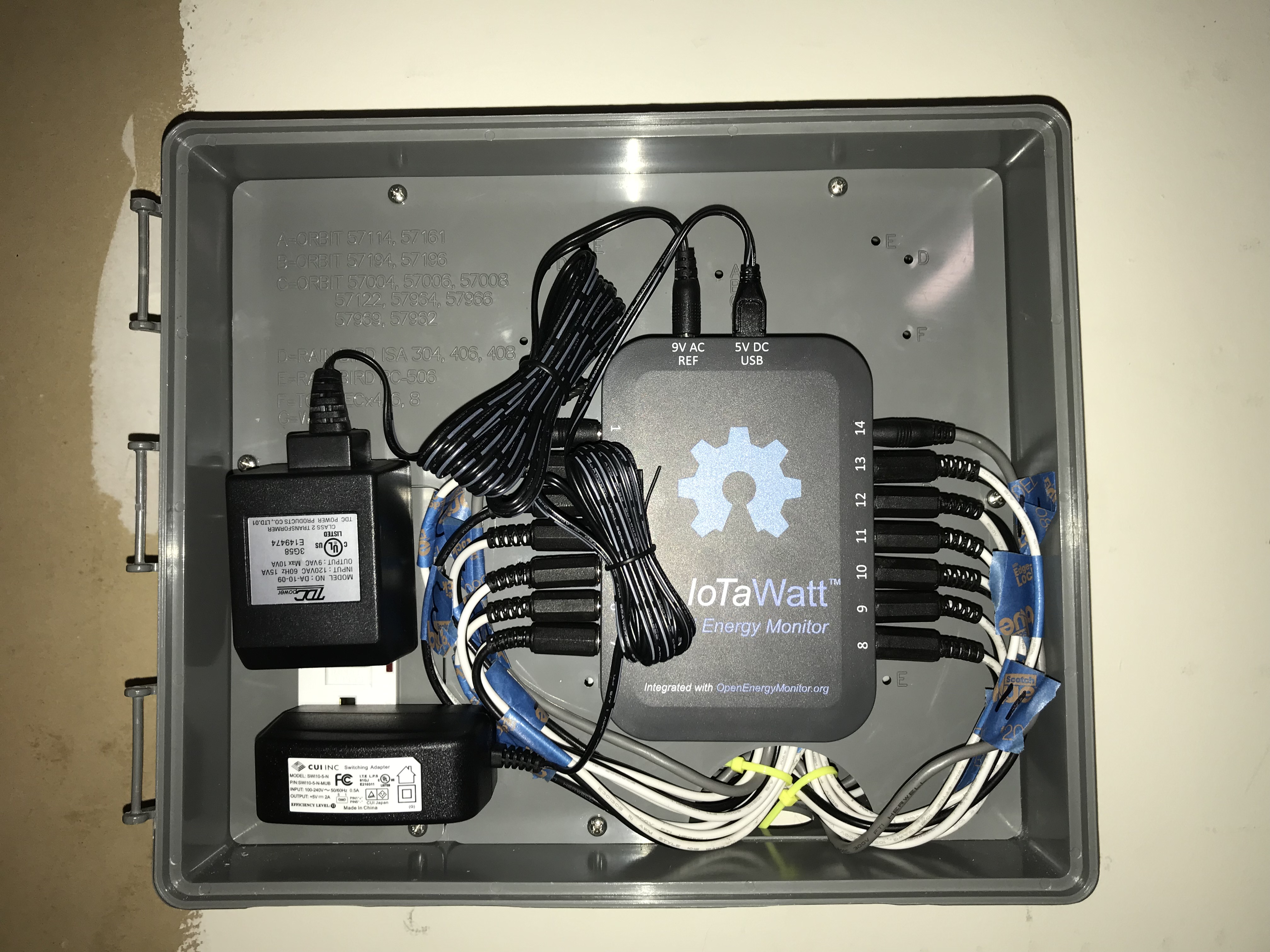
So to jump ahead, I wanted decent granular visibility into a majority of the daily uses, and which HVAC zones were active, while fitting into the 12 remaining channels somehow. I ended up making 2 spreadsheet table/maps: one is the set of 14 iotawatt channels with the CT or CTs that feed each and a few notes (and yes, I’d STRONGLY recommend labeling each end of every CT cable, I used a Klein label pack. $10 and worth it!). The other is the set of circuits I’m monitoring with their panel location, phase, CT # used, iotawatt channel, notes. I’d actually recommend first making a list of what YOU want to monitor, independent of exact circuits, CTs, channels, as you may combine circuits, CT outputs, and channels in interesting ways for yourself. Simplest example, I mostly do not care to see split phase A and B, just want to see total power.

I can share more of the maps if there is interest, not sure of best way to do that. Here’s what I ended up with:

image

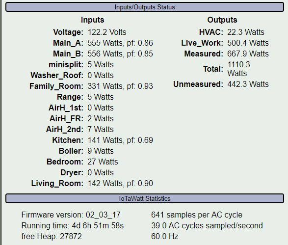
I used @overeasy’s suggestion to create an “unmeasured” output: mains minus all other channels, very useful.

I got some 2, 3 and 4 way headphone splitters to combine CT outputs. I ran 2 circuits through a couple CTs where that was possible and meaningful. I consciously evaluated some circuits and relegated them to the unmeasured category, so I know about 100-300 W in that virtual bucket. I combined the 3 AC compressor circuits using 2 CTs, double wired one, them merge with a splitter, but not using a channel until next summer. Combined washer CT with roof heaters, (2 in 1 CT), for winter. Combined 4 kitchen circuits/CTs into 1 channel with splitter, similar with living room, family room, bedroom areas, then those into the Live_Work output. Of course combining circuits reduces granular visibility, but I already understood what some of the components looked like - fridge is steady mostly-on 150W, microwave is short 1500W bursts, espresso is 1000W steady heatup then bursts as boiler cycles or make a cup. You can see this below.

Here’s one snapshot sample for today’s use, and now this posting is long enough! Can discuss and post more later if interest.

Note: I also set up emoncms on an RPI to feed iotawatt data for historical, also try to figure out how to log fuel oil consumption based on boiler burner on-time and G/hr rating of burner nozzle.

John

1 Like

Thanks for sharing your experience. Nice project.

I have been doing this for years with a Hobo datalogger. It uses a magnetic switch so I just stick it on the burner motor and it records when the motor runs. Your burner nozzle rating is dependent on age and pump pressure. To calibrate, record the burner time between fills and compute the actual rate. You can accumulate the data starting now and retroactively calibrate.

1 Like

Might have to go that way. If I did, I could free up that channel, combine into another HVAC-related channel. Still nice to see when burner runs for heat vs. hot water. Need more conditional test capability to really do that automatically.

Figured burner has own channel, draws 250W when running, almost nothing when idle, so I have emoncms (on RPI) process that “should” count time when draw is over 100W, and then math to convert run time into gallons, but can’t see how to accumulate those gallons over time like kWh are accumulated, and the ontime function does not do what I thought it did, help info is hard to find, the programing process is very quirky and limited, I always have to remember how the UI works, how the inputs, feeds, virtual feeds all tie together or not. Might reach out on that community, or give up :slight_smile:

1 Like

You may be able to work some of the math out using virtual feeds based off the inputs, etc. I have also been interested in the measuring of out fuel oil tank amounts, and have seen a few people that have built out a few ESP8266 modules with ultrasonic sensors mounted in the top of the tank (via some of the plugged holes. They use this to measure the liquid depth and based on how far it is from the sensor translates to the amount of fuel you have in the tank.

As you said, for measuring flow usage, you could take the data sheet from the burner you have and translate usage based on some estimates of flow from the manufacturer. I was looking more for a way to keep track of the amount rather then flow.

I was looking at something like this:

or this:

Here are some pictures of my IoTaWatt installation. This is a Sub-Panel in my garage, which has mainly 120VAC loads. The 240VAC circuits are primarily handled in the outside Main-Panel (will need a second IoTaWatt for that panel :wink: )

Sub-Panel

Inside

I used an Orbit Sprinkler enclosure, as it is the perfect size, has room for cable management under the main surface, and has a built-in GFCI Outlet. I had to add a 15 Amp breaker to my panel to feed this enclosure with power for the IoTaWatt.

I used 1" smurf tube for the CT cables. It was snug, but all 14 cables fit.

Here is what the inside of the finished panel looks like.

And the wall with everything buttoned back up.

Thank you to everyone else who has shared their installation experiences. I got lots of great ideas from all of you!

2 Likes

Nice score on that enclosure. At first it looked pricey, but I didn’t realize it had the GFI duplex outlet. Very clean install, nice job.

1 Like

Yes, it is a little pricey, but it really works very well, and is designed to be used outdoors as a waterproof sprinkler controller enclosure. So, when I install the next IoTaWatt at the Main Panel, I know I’ll have a working solution. I’ll just need to figure out how to do the conduit between the two boxes. Unfortunately, the Main Panel is completely full of 6 x 240VAC breakers. So, I am not sure where I will be getting the 110VAC needed for the IoTaWatt’s adapters.

Check with an electrician, but I think it’s copacetic to use one leg of a 240 breaker along with neutral if you have a 20A or less 240 breaker.

1 Like

Very nice and clean install, thanks for sharing. I like the conduit run as I would have thought the surface mounted box would have been hard to make connection. Wires are labeled and the ties keep is very professional looking. It looks great.

1 Like


Orbit sprinkler box installed. Two outlets for each Vt to plug into. Iotawatt should be here tues.

2 Likes