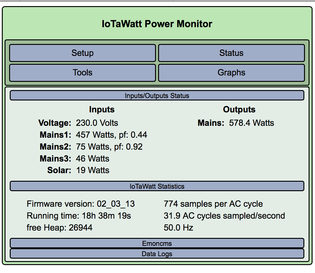
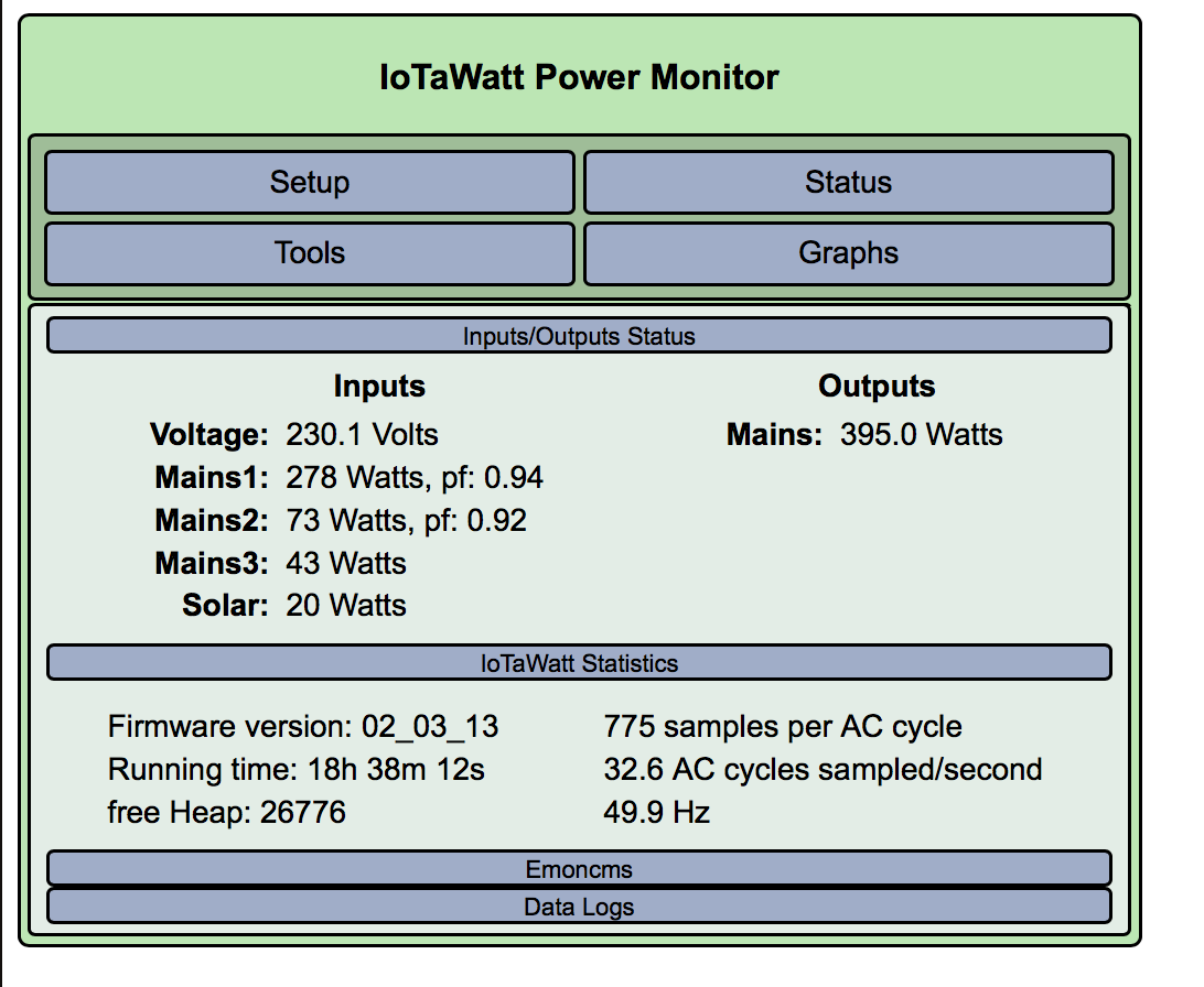
This experiment was just to determine if there was anything unique about channel 1 of the IoTaWatt, to rule out a problem there. Although all of this does open up new questions, I think it does indicate that the IoTaWatt is working fine.
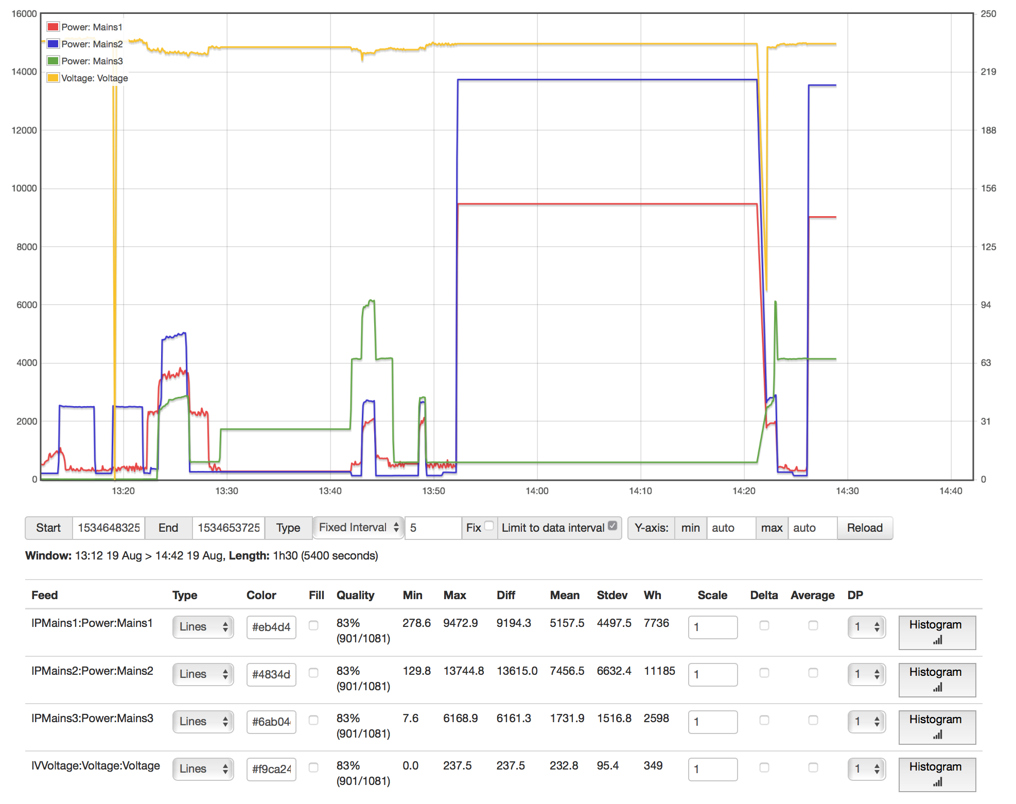
We swapped channel 1 and 2 to see if the low readings on channel 1 with the AC running moved with the CT. It did. If it had been the channel, mains 2 would have gone low and mains1 would have gone higher.
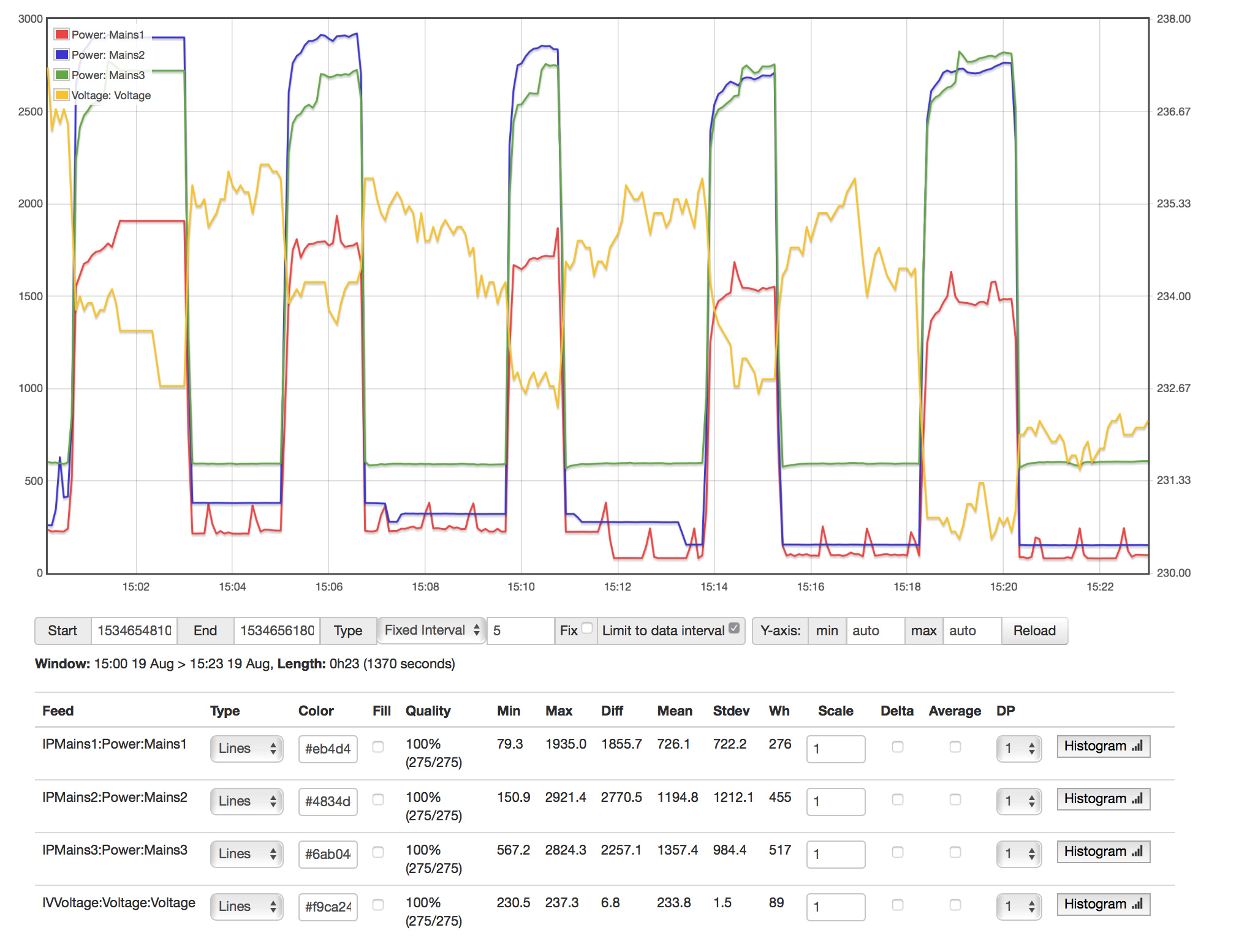
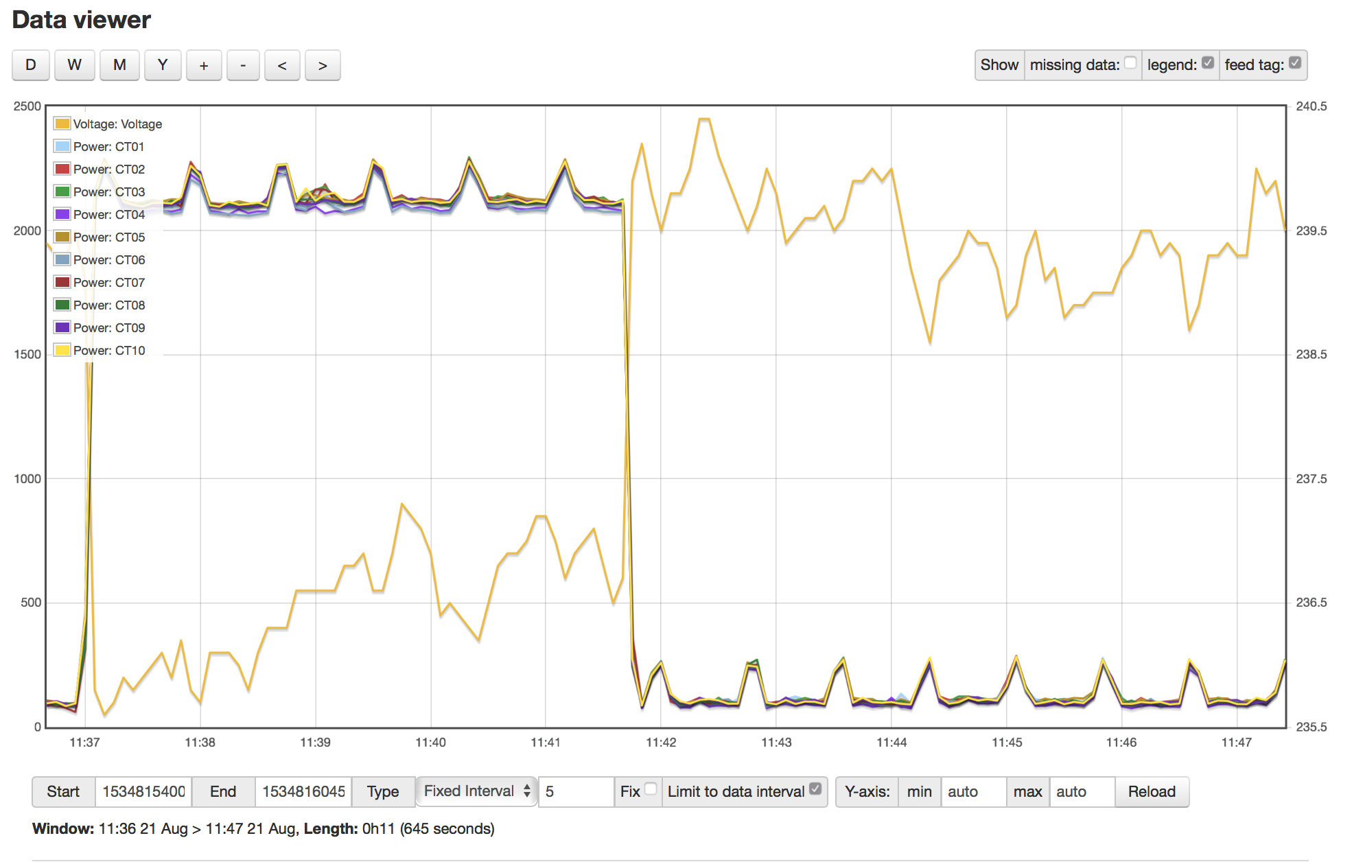
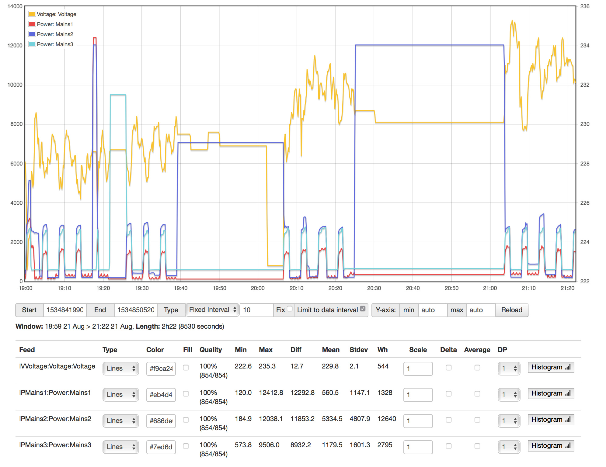
Another clear indication that the channels and the CTs appear to be working properly is the graph with the sauna. That appears to be true three-phase around 12kW, and all three mains appear equal with that running.
Without examining the AC system, I can only speculate. I’m starting to think there are one or more single phase motors in there that cause the imbalance between mains. I’d expect the compressor to be three-phase, but maybe the air handler uses single phase blowers on mains 2 and 3. Regardless, I think the AC imbalance is a red herring with respect to reconciling with the meter.
I see that your system has updated to 02_03_13, and there may be a recurrence of problems with zero voltage. I changed some things because of other unexpected consequences. The voltage dips of 5-10 volts when high loads kick in is probably accurate in my opinion, but that Combined with the large load swings is increasing my suspicion that derived reference may not be appropriate for your setup.
Agreed - the Sauna shows that we get some balance across the 3 phases assigned and they are close. I suspect the AC has multiple single phase units combined - eg compressor/fans/etc Ultimately its not as issue as long as we can get a handle on the total draw.
I see that your system has updated to 02_03_13, and there may be a recurrence of problems with zero voltage
I am guessing this was because I am on ALPHA and did a power cycle to remove the laptop.
We have now changed the 3 x CTs on the mains with new CTs from a new batch.
We are still reading low and I would like to get that addressed somehow.
derived reference may not be appropriate for your setup
Not quite sure what you mean here and very happy to take direction.
I assume this means we need to get 3 x VT across the phases. We will have a second iotawatt soon but not sure how/where to confiture the 3rd VT.
I will do the CT test tomorrow to see if we have any outliers - will also list circuits and suspected phases for going forward.
Do the CT test/audit on Mains1 (PhaseA) circuit with as many CTs as I can practically fit there and then post results. - audit all of them so I know if we get any outliers. (I can also get a TrueRMS clamp if needed to confirm whats really happening.)
Post a table of circuits (planning purposes - eg connecting CTs and VTs in preferred fashion)
Why (I want to get input as to how you want me to configure them as I we will be using at least 2 and possibly 3 iotawatt units).
Background Stuff
a) There is another IotaWatt coming with 2 x new VT. Will test to see if we get anything different on the Voltage reads (it also means I have 2 of the same units and can compare against my current though I understand it shouldn’t make any difference once calibrated.)
b) Also awaiting instruction/thoughts from @overeasy re derived reference / other approach to monitoring.
Once we have a plan for configuration that seems to work, I will organise an electrician to come in and clean up the installation and run me another external power point setup (so we can nicely mount the VTs/iotawatts/cables/etc) I was hoping to defer this until I had some readings as I think I want to significantly upgrade my solar but wanted to get some stats first. Should it be needed we can also trace phases.
Table for Planning:
Circuit
Phase
amps
CT
IotaWatt-Unit
IotaWatt-Input
InputName
Notes
Mains1
TBC
nn
Mains1
Mains input/service fused
Mains2
TBC
nn
Mains2
Mains input/service fused
Mains3
TBC
nn
Mains3
Mains input/service fused
Solar
TBC
20
Solar
Volts read high at Solar Inverter (240 vs 230 at box)
HotWater
TBC
20
HotWater
Single Phase
Aircon1
TBC
32
Aircon1
3 Phase input / single breaker
Aircon2
TBC
32
Aircon2
the aircon doesnt seem evenly balanced across
Aircon3
TBC
32
Aircon3
all the phases
Garage1
TBC
32
Garage1
3 Phase input / single breaker
Garage2
TBC
32
Garage2
Workshop and Sauna
Garage3
TBC
32
Garage3
Sauna
Sunroom
TBC
20
Sunroom
Sunroom/part of recent renovation
Shed1
TBC
32
Shed1
3 Phase input / single breaker
Shed2
TBC
32
Shed2
Fridge room
Shed3
TBC
32
Shed3
Pool pump/setup (need to check out)
Lights1
TBC
16
Lights1
House lights - these circuits are close together and
Lights2
TBC
16
Lights2
if they are on the same phase we can use a single CT
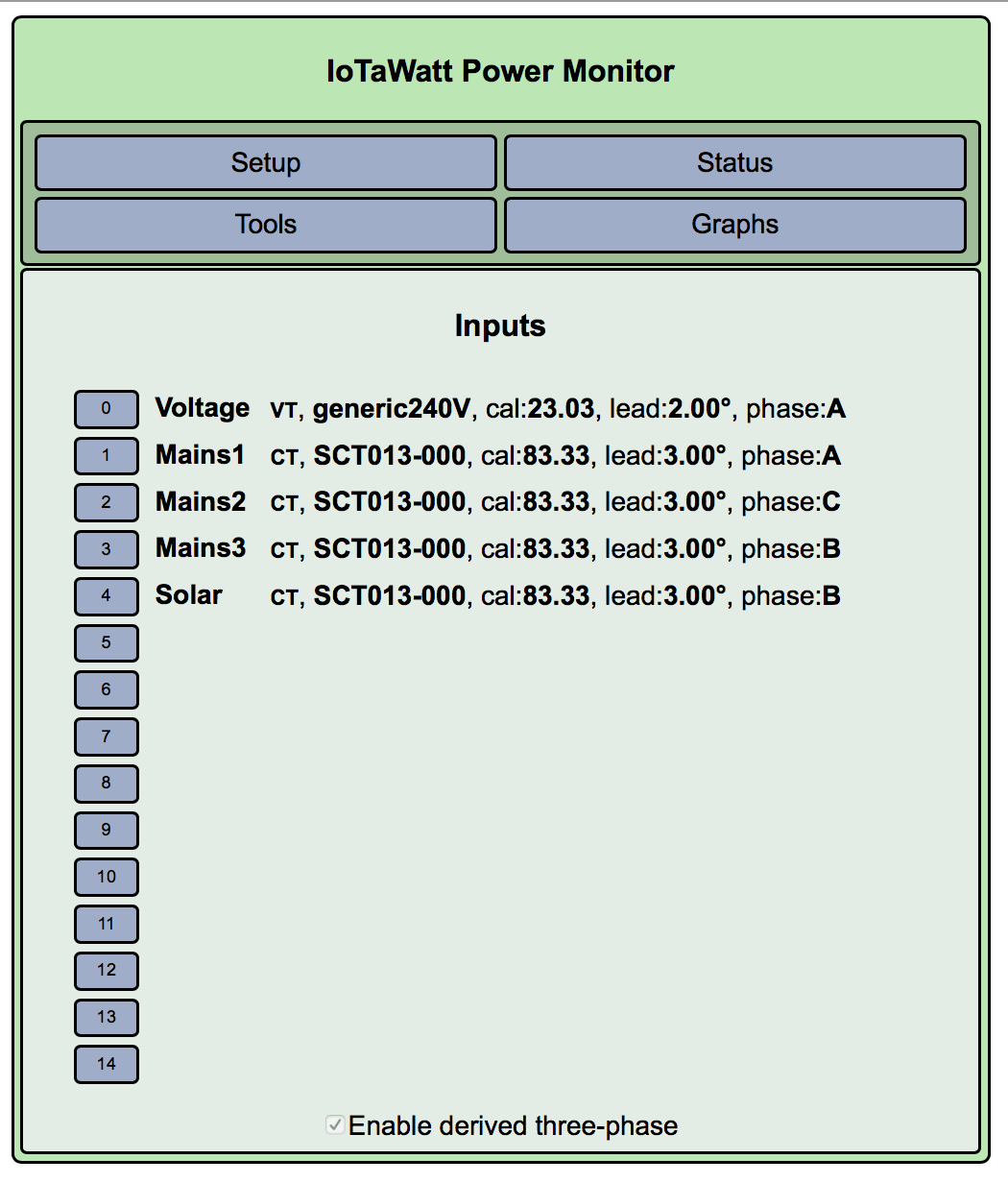
IotaWatt Configuration:
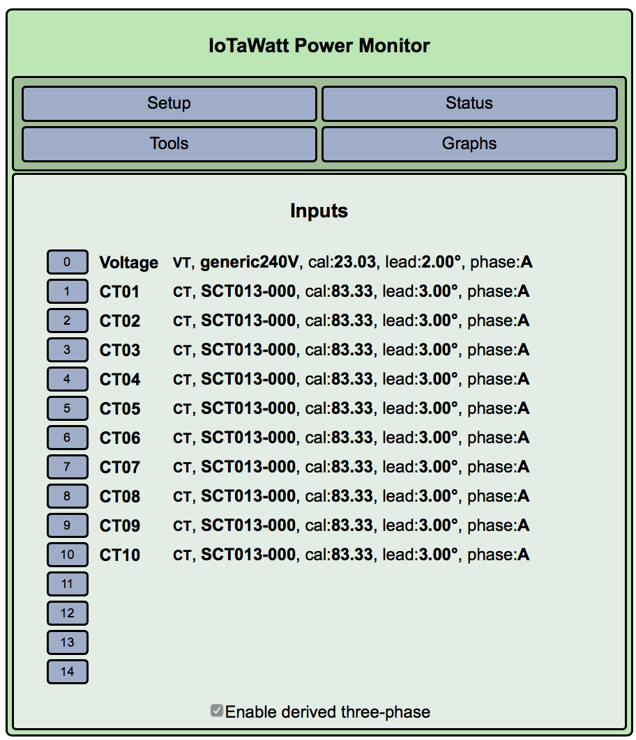
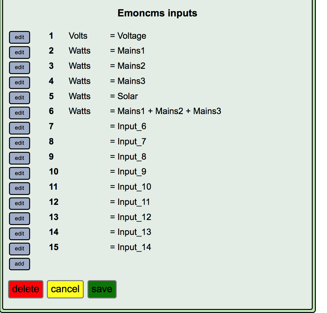
Cleared the inputs/outputs and suspended logging to emoncms.
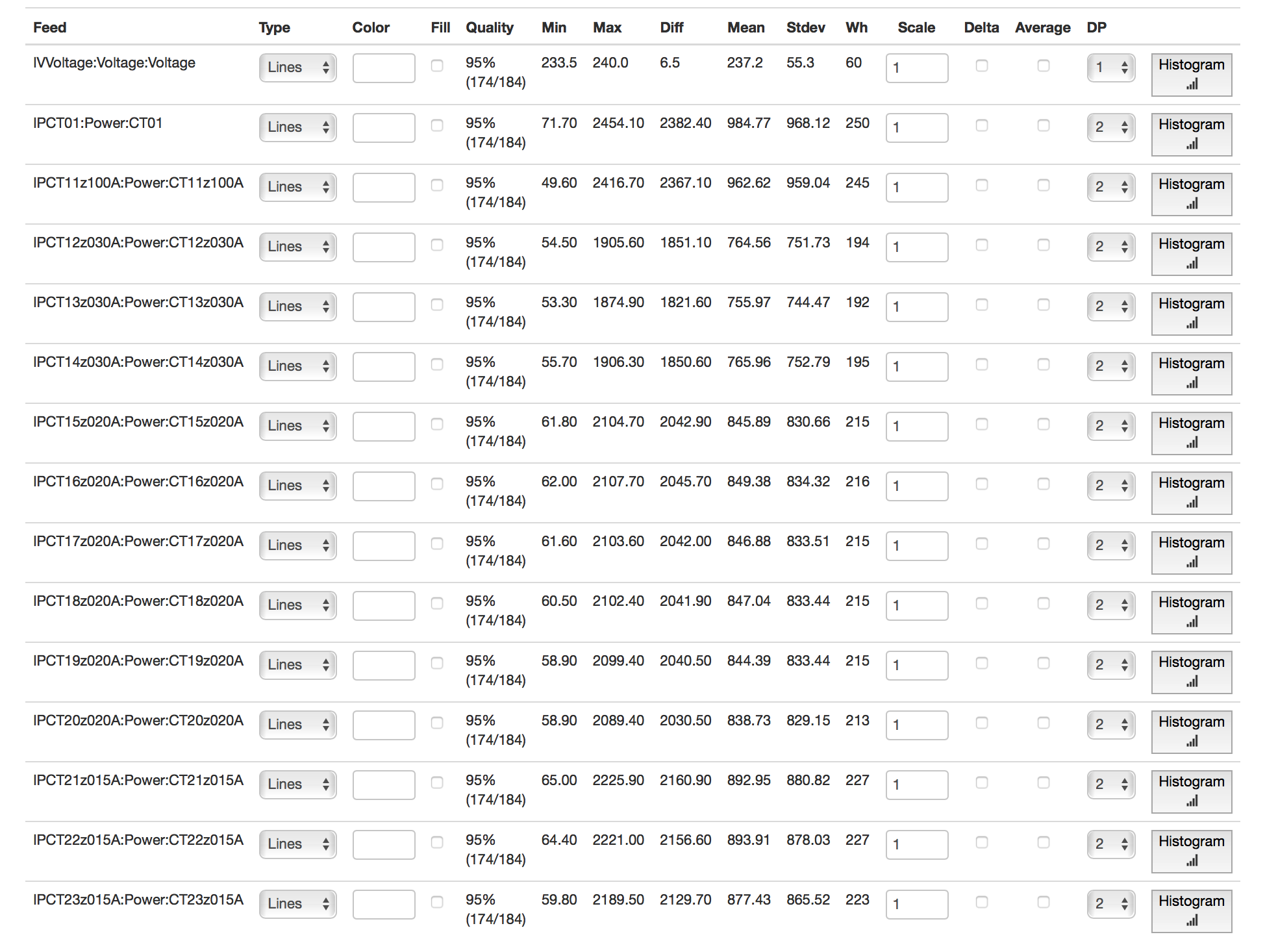
Numbered all the CTs from 01 (I) upwards to 23 (XXIII)
Named the inputs to match the CT.
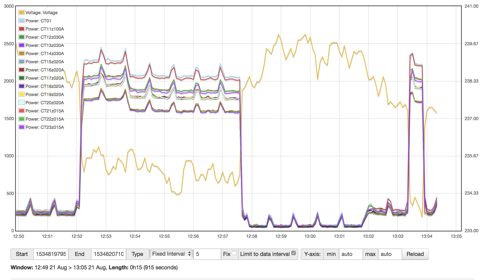
Am using house power and boiling a kettle to generate ~2000W as the high load.
Testing CTs - Batch01
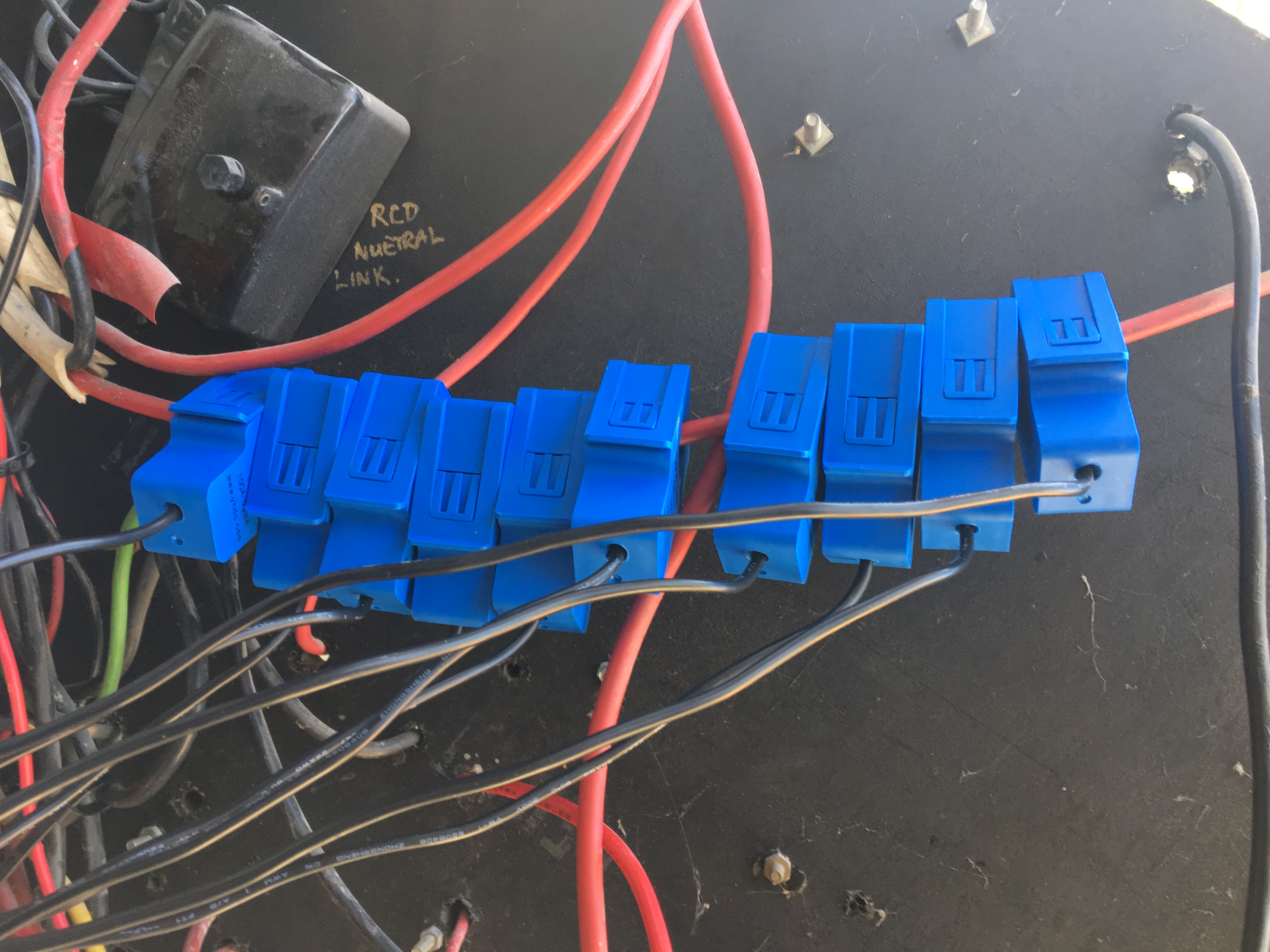
This is the second batch I received and are CTs that we have been using most recently to monitor the Mains1/2/3 and Solar inputs for discussion/testing.
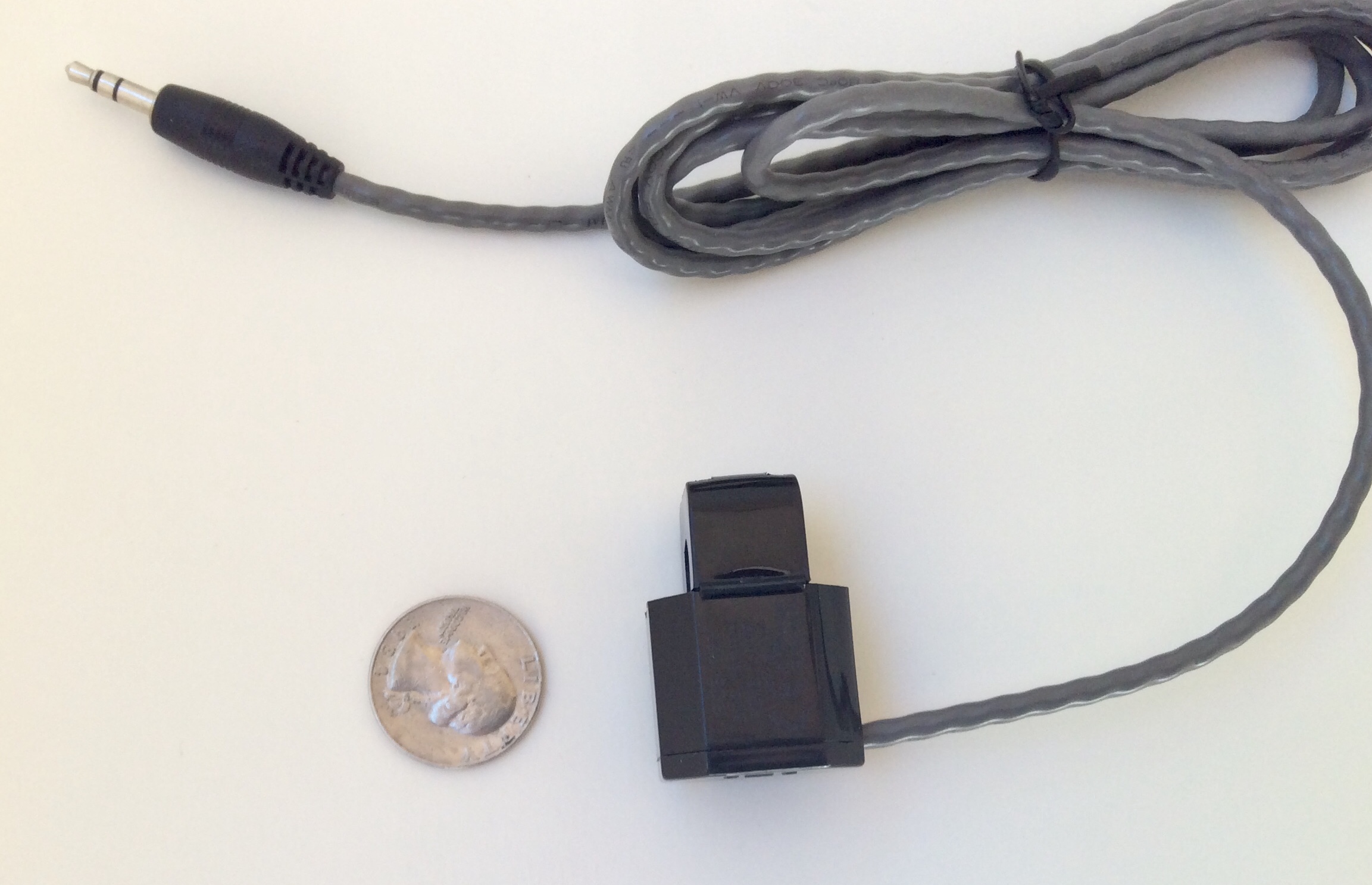
SCT-013-000 Non-invasive AC Current Sensor Split Core Transformer 10 x 100A:50mA
That’s the problem. Those are “voltage” type CTs, they are not SCT013-000. They have burden resistors, which when combined with the burden in the IoTaWatt, present a lower overall burden and thus a lower voltage and so indicate a lower power. Moreover, those particular CTs have fewer turns than the SCT013-000 at 1860 vs 2000. Your problem has been the IoTaWatt reading lower than your meter. This explains it completely.
You should not be using those CTs. Install the new ones on your mains, solar, and hot water and see if you get better agreement with your meter.
There were SCT013-000 originally on the mains but they were from the “old batch”.
The new ones are from a different supplier and have a slightly shorter, thicker cable and all read the same.
I had been told to purchase the other units as it was better to match the circuit with the AMPs from the CT as it should have been more accurate".
Having run my experiment and also found this thread, that logic proves to be incorrect when used with IotaWatt hardware.
I did read the doco prior to purchase but this caught me out and it might be worth an additional note on both sites that not all SCT013 are the same or usable.
I am happy to pm you or post the source I found for the CTs as it might be useful for other aussies.
Once we have our Inputs//Meters lined up I can order the others I need and place with more confidence.
Going Forward
I have installed the “new CTs” on Mains A/B/C and Solar as this is what I can reference meters against. It will take another 24 hours to be able to line up with the meters as I have been logging my meters at 10:00am in the spreadsheet. I will report back.
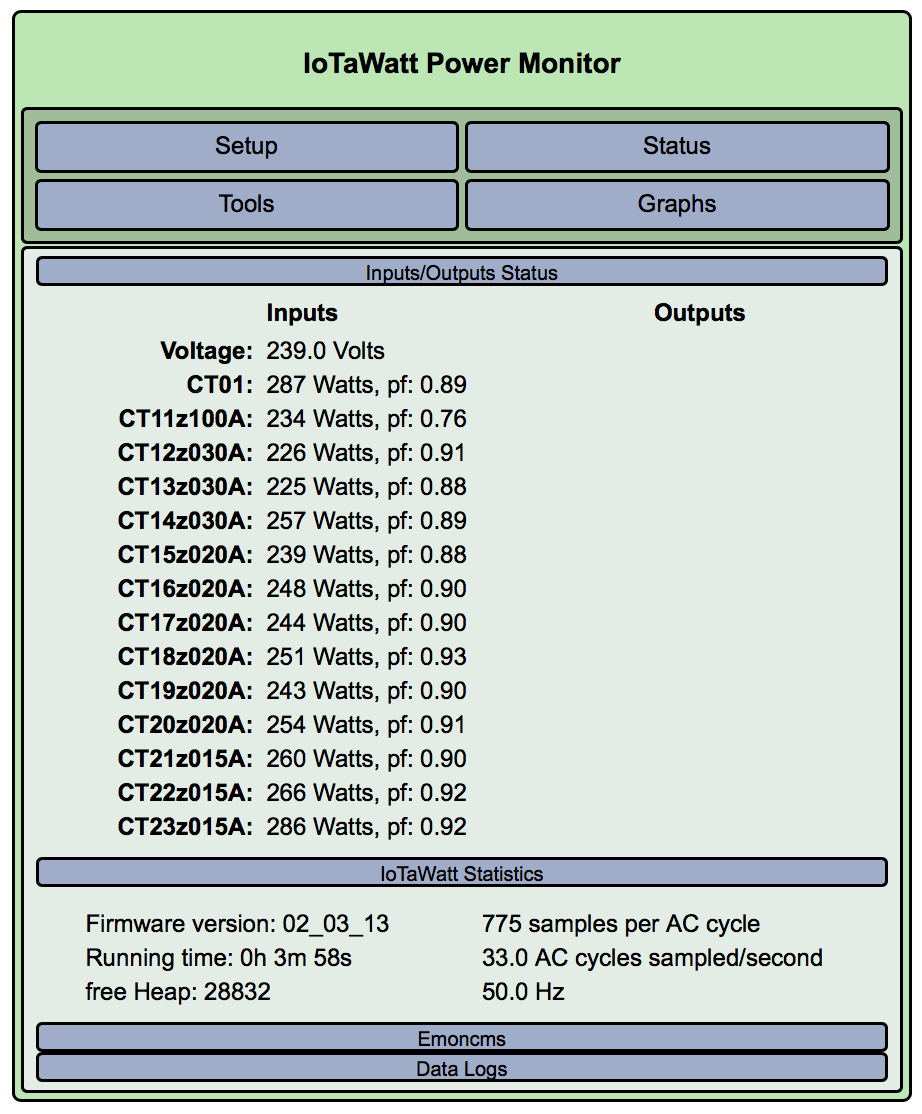
I have validated that with load on known circuits for A/B/C that Iotawatt reads 1.00pf (at ~2000W) eg moving the kettle.
I can see about 680W on Solar with pf1.0 which is closer to what the inverter tells me its making. (Still about 75-80% though).
The pf for PhaseA does fluctuate a little between 200-400 watts (washing machine on pre wash).
This may be normal - its when the load decreases over time vs load stopping (eg motor reducing RPM over 30 seconds). I don’t know if its an issue but mentioned it for completeness.
I cant comment on PhaseB/C as anything that fires up starts around 500W and it locks in pretty quickly.
V[quote=“bluetardis, post:70, topic:248”]
There were SCT013-000 originally on the mains but they were from the “old batch”.
[/quote]
Not to put too fine a point on it, I believe the correct models for those voltage type CTs is SCT013-050, SCT013-030 etc. Educating the world about the confusion isn’t anything I’m in a hurry to do, although I’ll be more aware of the possibility next time I get a low reading inquiry.
While the SCT013-000 works fine, I don’t recommend them. I’ve tested all of the CTs you see listed in the config Dropdown with a special rig that measures linearity and produces a phase shift profile. The Echuns, in my opinion, are superior in just about every way, and they have UL and CE certifications. I’m not aware of any certifications for YHDC CTs.
I’ve seen quite a bit of advice handed out that encourages careful CT and burden matching to get optimum results. While the case can be made academically, I’ve yet to see where anyone has actually shown any imperical evidence that it matters. The proof of the pudding… Maybe I didn’t look hard enough. I’ve run 800, 1000, 2000, 4000 turns on the same wire and had equal results.
In the test that you did on one wire, there were some outliers At 2% of the average, but in a true test you would need to space them an inch or so to eliminate interference.
If your solar is still low with the meter after a couple of days, try changing the CT.
Don’t get hung up on power factor. Unity (1.0) is useful for sorting out the phases, but the problems you Were having with voltage type CTs should not effect PF.
I will need some more CTs so lets get the right option.
While I do have some space in the back of the box its not massive. I want to get a lot of CTs in there to determine “what” is draining power. AC is a culprit but there are some unexpected heavier usage that needs to be traced/ongoing monitored.
Biggest cables are 6mm - I think I saw a post where you had recommended some smaller Echun? Can you please confirm model and I will see if I can source a batch of them?
I get it - just can’t find any local supplier for Echun whereas I can get the SCT13 locally.
Price is similar so happy to get either - just wanted to make sure I had right unit.
I can purchase from you but I think for 30 CTs thats likely a major hassle with double shipping etc. Let me know.
I will post an update tomorrow.
My computer has crapped out and needs a service. Still logging though.
Good news is that we are closer.
Against the meter, Solar is about 90% mains is about 110% of metered reading.
The solar might be ok, just that we have 2 decimal places on the IoTaWatt and 0 on the meter.
Have moved VT input calibration from 23.03 to 23.09 and tracked it against multimeter over 10 minutes. It was accurate when we initially installed but with updates, etc I figured it was worth repeating the process.
Not too clear on that 10:00 check in time, but over a few days, should not matter. Post the data after you get back on the air.
Yea, that’s 0.2%, which I’m sure is better than the multimeter spec and definitely more accurate than the derived voltages being used for two your three phases. So don’t obsess about that.