Sorting out an Australian three-phase installation

Not a lot to go on here, but certainly seems directly related to the AC unit. What sticks out to me in the above graph is:

  • The lapse at about 15:18 seems to begin when the AC comes on, and continues for a few minutes, then starts working again before the end of that AC cycle.

  • The lapse at about 15:24 also seems to begin when the AC would have come on, and ends about where the cycle ends.

  • There is another anomoly at about 15:53 where mains1 spikes briefly. That is inconsistent with the other normal cycles.

Iā€™m assuming that the AC actually ran during the first two lapses, its just that the IoTaWatt wasnā€™t measuring anything. Even in the graph from yesterday, the voltage was not being measured properly.

By elimination, I conclude that what is going on is that the voltage signal is not symmetrical during those periods. One of the ways IoTaWatt checks the viability of a cycle sample set is to compare the number of samples taken between the zero crossings i.e. the ā€œpositiveā€ and ā€œnegativeā€ portions of the voltage cycle. If they differ significantly, the entire sample set is discarded. This is one of several integrity checks on the sampling and is intended to detect if an interrupt compromised the sampling. So the question is what could be triggering that?

Iā€™m getting away from my comfort zone speculating about what is going on with this relatively complex AC system, but Iā€™ll just throw a few things out there. Maybe theyā€™re valid, maybe not:

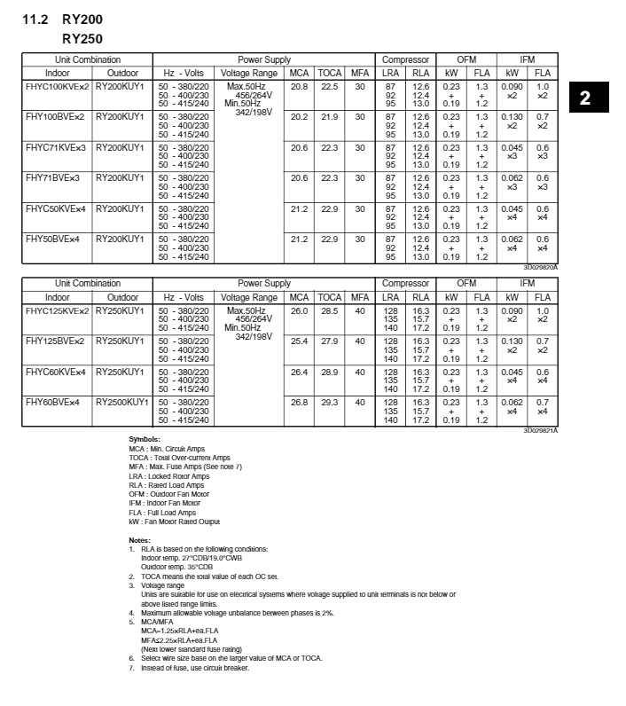
Given that everything comes on at once, there is probably a tremendous inrush current. Looking at the Locked Rotor Amps of the compressor, it can be as high as 105 Amps. We are seeing about 42 amps at the time of the event, but that is an average potentially over a few samples, so it could be much higher for one cycle.

So it could be a starting issue, especially looking at that 15:53 event (and the tail end of the preceding cycle). Maybe something with a relay, or a capacitor in the starting circuit of one of the single-phase fan motors.
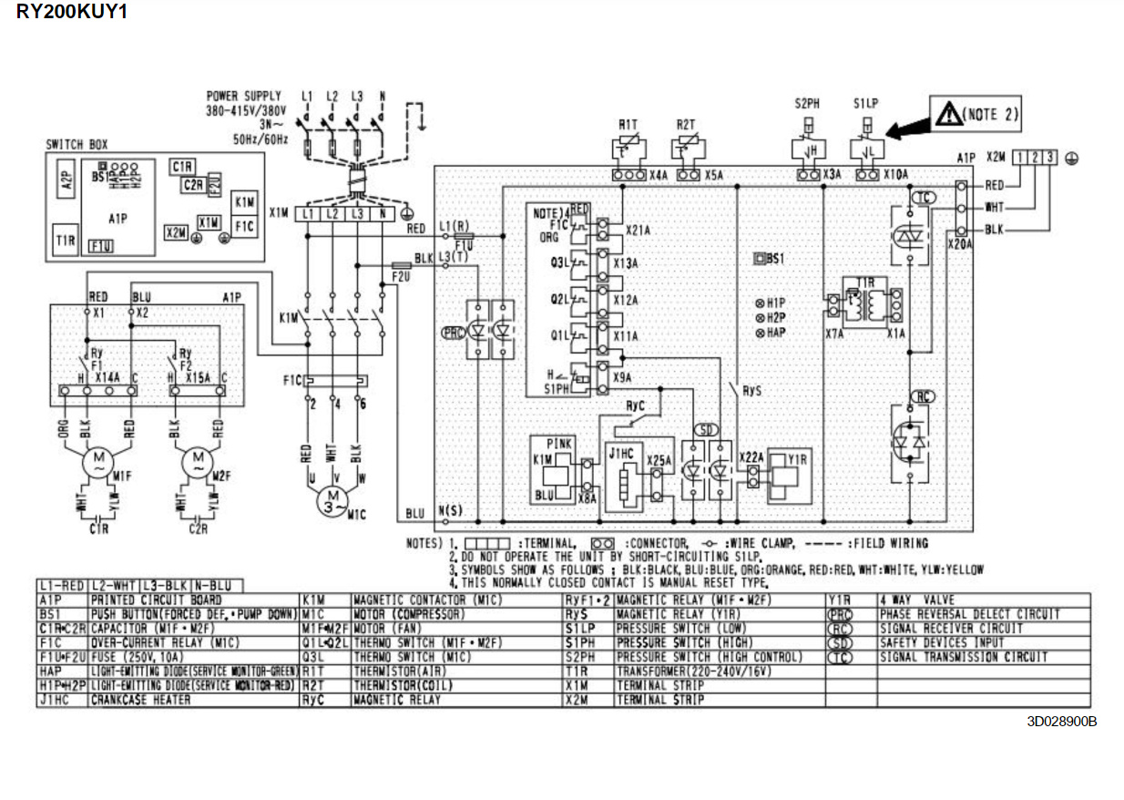
Iā€™m also wondering about why the electrician mentioned a ground problem. Given that the compressor is delta wired (400V), the line of phase A (the VT) is connected to both of the other phases while that motor is running. If the ground is bad, I think the voltage could swing back and forth toward the other phases on a cycle by cycle basis and cause the asymmetry that would trigger this problem. This is not the macro level voltage that you see in the graph, Iā€™m talking about the actual voltage during each individual cycle. It could even work out to a decent RMS voltage, but just not symmetrical enough to be acceptable to IoTaWatt. This could be a broader three-phase issue, although there has only been one other problem that might be linked. I can raise the threshold that triggers the sample rejection and see what happens.

The other issue that hasnā€™t been mentioned recently is the ā€œflickeringā€ that was previously reported. My suspicion is that these two are related.

So going forward, Iā€™ll change that threshold in the next release and see what happens. Maybe even put in a temporary way to set it in the configuration so we can experiment.

You will have the electrician check things out, although I suspect the issue is in the AC unit rather than the general wiring as itā€™s intermittent.

@overeasy many thanks for looking at this.

Not sure why it decided to behave more yesterday and I can repeat it and leave it for a longer period if needed.

The AC did run but would have been cycling on/off.
I agree that on startup the current is very high. Short of getting a truerms clamp meter I donā€™t have a way of measuring it. Itā€™s also on the startup we get a voltage sag in the house thatā€™s enough to upset anything sensitive eg reboot PlayStation.

Lights flickering - I will be working on that but I suspect itā€™s due to our using non dimmable power efficient lights and them turning off/on as the voltage sags and recovers.

He mentioned a possible neutral problem based on his experience/gut feeling. Will know more after his visit. Either way we will have everything tested and labelled so going forward we are in a much better position.

So going forward, Iā€™ll change that threshold in the next release and see what happens. Maybe even put in a temporary way to set it in the configuration so we can experiment.

If you do this - let me know and I can plug the laptop back in. If there is a way to get more verbose information let me know and I can turn it if it helps.

1 Like

Soā€¦ Here is the updated graph.

We are tracking ok - unless the AirCon is used.

Next Steps?:

  1. Electrician coming Monday (goals are check of meter boxes/cabling, identification of phases/circuits, check of ac)
  2. Update the list of circuits etc. and agree a plan for configuration of 2 x IotaWatt for VTs, CTs and inputs.
  3. Perform testing as recommended etc.
  4. DRAFT dashboard (via private hosted emoncms/influx/etc.)

@overeasy I have the electrician coming Monday. Amongst other things I am getting him a to install an external power point (phase A) that I can use for my permanent mounting. Should I get additional points for Phases B&C if itā€™s not cost prohibitive or hold off as hopefully we wonā€™t need them.

Currently I can access phases B and C from a gpo in the other 2 boards (shed and garage)

Completely up to you. It looks like the derived reference is about 2-3% off from the meter, but we donā€™t know how accurate the meter is, so we donā€™t know if direct reference would be an improvement. Then thereā€™s the problem that you donā€™t have VT adapters and I donā€™t supply them. So maybe Iā€™d recommend you leave a spot to put them later and have the electrician come back if you decide to make the leap.

leave a spot to put them later and have the electrician come back if you decide to make the leap

Good call and thanks for the quick reply.

I did a quick total of meter vs iotawatt for all days without significant testing of aircon and the meter vs iotawatt is within 1% so happy to call it a day.

When we go with the second iotawatt is there a recommendation eg I run an adapter from the transformer so both iota watts are fed from the same VT reference?

Yes, I would recommend you get a commodity DC power splitter for the VT These are common in the CCTV market and elsewhere. They usually cost about $5 US tops. One of these will insure that polarity is the same going into both IoTaWatt.

You should, however plan to use two USB power supplies.

Thats the plan - I have 2 x Raspberry Supplies for the USB Power and its easy enough to get that other part.

I will update once we have a few more days but more importantly the list of Phases/Circuits and anything the electrician found/fixed.

@overeasy - reporting back post electrician visit.

  1. We have all phases noted and identified across circuits and I will update a table and post pictures later. For now we have mapped A/B/C for consistency however it actually appears to be A/C/B from a phase perspective.
  2. The AC appears to be ā€œstuffedā€ to use a technical term. Dead short in roof unit across phases and it will need some love. Short term its going to stay off at the breakers. Long term - we will get it looked at but its likely to be replaced if needed once budget becomes available. Using a slow combustion wood heater for now.
  3. It looks like the solar hot water in the roof isnā€™t making a lot (if any) hot water. Will give panels a good clean and get it checked but the hot water booster has been coming on a lot and is possibly the main use of our power. (Its pulling 3600w a lott with no off peak available.)
  4. Voltage Reference optionsā€¦ Plan is to clean up the main board (when we get the solar on) and this will replace both the old 3 phase meter and solar meter with an integrated nett meter. Also they will be adding 3 x GPO on rails within the board that we can use for reference. (This is likely 30+ days away).
  5. We may need 3 phase direct reference as PhaseA = 230v, PhaseB=240v, PhaseC=245v - That saidā€¦ the overall reading (meter vs iotawatt) remains pretty close and if its within a few percent its probably not worth worrying about.
  6. Neutrals have been tweaked as they werenā€™t bad but they didnā€™t make good use of contacts available.

I would like to get an understanding on the following: (so we can work out whats pulling power and plan for solar and or batter):

  • shed usage (we have a few fridges in there and want to know if there is anything using extra power)
  • hot water system (likely the culprit for power usage but unknown)
  • oven (old oven that takes a while to come up to temperature)

They (several companies quoting) are keen to get some more data in order to come up a good solar option.

If you are ok with it, I will test the Echun CTs for consistency then get a handle on usages on some of those circuits. Starting with a few CTs and then adding more as needed till we figure out whats chewing power.

1 Like

I have to wonder how that can happen without a breaker tripping, but it is good to know it was a serious problem that effects voltage.

The proof of the puddingā€¦

Iā€™ve found this https://pvwatts.nrel.gov/ to be a good tool to size a solar array. Donā€™t know how well it does the Southern Hemisphere, but worth a look. My experience is that it pretty reliably predicts kWh within 10% of the first year production.

Yea sure. The training wheels are off. I think youā€™ve got it figured out now. Iā€™d caution that you develop a discipline for orienting the CTs correctly. Determine the line-load orientation and stick with it. Good luck.

bluetardis:
We may need 3 phase direct reference as PhaseA = 230v, PhaseB=240v, PhaseC=245v - That saidā€¦ the overall reading (meter vs iotawatt) remains pretty close and if its within a few percent its probably not worth worrying about.

So here is the current read for the last few weeks. I have also taken a sum of most of the days (I have excluded the first few where we were testing CTs then ran a 8hour air concession as that data is rubbish)
so summed from the 25th onwards. Totals are in bold at the top

The totals are within 2% (and thats with some AC testing which we know screws things up). I think without it its closer to 1%.

I donā€™t have a cost to put A/B/C GPOs in my box but I think we will probably get this done when the meter gets updated so they are there for the future in case we ever need direct reference however my plan for now is to keep using Phase A.
The Phase C will always be higher as its connected to solar which is aiming for a little above 240v. When I tested earlier, I was seeing 230v at the GPOs for Phase B/C for the other boards so it probably does move around somewhat.


There is also quite a difference in size of the units. I am inclined to leave the SCT013-000 on my Mains and replace the others with the Echun for additional units. For now I am only using some for ā€œdetectiveā€ work but I will need to get some input as to the best way to utilise 2 x IotaWatt and the metering I have for a full read.

I donā€™t buy the AC argument because your number is low and the AC problem was too high. That said, the last 8 or so days are promising and in the 1-2% ballpark. So Iā€™d say stick with derived for now. Besides, you get 4 more inputs that way.

Definitely. The Echun are only 50 Amps. Your mains will probably exceed that from time to time.

Soā€¦ the days I ran the AC in there were only a few hours. Not sure why the totals are out a fraction. If I include everything post the CT test it looks like the following. (That had AC on most nights for heating)

Besides, you get 4 more inputs that way.

Agreed. Going forward I am going to do this as it fits within one IotaWatt and gives me biggest bang for my buck for detective work.

That said, I have purchased a second iotawatt and CTs (SCT013 and echun5010) to populate both as needed (post final install of solar/etc.)
As always I would appreciate your input into best way to configure across both units (but I was going to leave the install of the second unit until after the mains/solar upgrade was complete.)

Table for inputs below:
(I was assuming I would need more reference for PhaseA/B/C and wanted to have all circuits measured).
For CTs, S01 = SCT013-000 number 1 and E01 = Echun5010 number 2
Board = Marked on Board vs what we have determined the phase to really B and I need both so I can reference the install and then configure. In reality A=A, B=C, C=B.
This way I can start logging whats using power. I donā€™t care about the sauna as we know its working fine and what it draws when it gets turned on.

Circuit Board Actual CT IW Input InputName amps Notes
Mains1 A A S01 1 1 Mains1 80 Mains input/service fused
Mains2 B C S02 1 2 Mains2 80 Mains input/service fused
Mains3 C B S03 1 3 Mains3 80 Mains input/service fused
Solar C B S04 1 4 Solar 20 CMS2000
HotWater C B E01 1 5 HotWater 20 Single Phase
Aircon1 A A Aircon1 32 3 Phase input / single breaker
Aircon2 B C Aircon2 32 the aircon doesnt seem evenly balanced across
Aircon3 C B Aircon3 32 all the phases
Garage1 A A Garage1 32 Sauna
Garage2 B C Garage2 32 Sauna/Lights/Workshop
Garage3 C B Garage3 32 Sauna
Sunroom C B E02 1 6 Sunroom 20 Sunroom/part of recent renovation
Shed1 A A Shed1 32 3 Phase input / single breaker
Shed2 B C E03 1 7 Shed2 32 Fridges Power/Shed Light
Shed3 C B E04 1 8 Shed3 32 Pool pump/setup (need to check out)
Lights1 B C E05 1 9 Lights1 16 House lights - these circuits are close together and
Lights2 B C Lights2 16 Sharing a CT across both circuits
House1 A A E06 1 10 House1 20 will map/figure out and give a better name
House2 A A E07 1 11 House2 20 will map/figure out and give a better name
House3 A A E08 1 12 House3 20 will map/figure out and give a better name
House4 A A E09 1 13 House4 20 will map/figure out and give a better name
Oven B C E10 1 14 Oven 20 Basic 20A Single Oven on Circuit

Pete,
saw this - seems to be legit but the FAN motors according to this, are connected phase to neutral i.e. plain old single phase. I didnā€™t notice a neutral link in the box but it must be there to connect the earth and RCDs. Anyway it doesnā€™t explain the phase which is using much less power once the A/C is on. If the fan motors was connected across 2 phases then 2 of them would (as your graphs show) read high. If the fan motors are between 1 phase and neutral, only one phase would be significantly higher. I donā€™t think the fans in the coil (indoor) units would use that much. It doesnā€™t make much sense.

Interesting that the control board is across phases not single phase.

No idea how you can have 1 (or) 2 phases shorted in the roof. Should blow every fuse on that phase(s).

I agree and thats where the 2 electricians stopped and saidā€¦ We arenā€™t air conditioning specialists and this is outside of our scope for todayā€¦but this is weird.

I saw them use a scope and meter to confirm it. They also then used (brain has gone on holidays) a gadget to inject 500v down the line to test across phases and neutral. They all shows that Aā€”C is theoretically shorted. Eg if they disconnected the roof unit then all readings are as normal/expected. Reconnect wiring to roof unit and short is indicated.

From the diagram, the indoor unit is continuously connected (as long as the breakers are closed). Measuring across phases would show the resistance of the internal components in the controller. If there is a transformer involved then they are measuring across the device. Donā€™t know how many ohms but a DC measurement, as opposed to impedance, may be just a few ohms which may seem like a short. The device with 500V may be a ā€œmeggerā€ used to test insulation quality. The megger bit comes from ā€œMeg Ohmsā€ measurement.

Iā€™d be real nervous about anyone ā€œmeggeringā€ a control device such as an A/C controller. Short path to a dead device IMHO. Lots of devices, including most solar inverters, state ā€œdo not use a megger to test this deviceā€. Diodes just donā€™t like high voltages applied across.

Here is a fun chart - it shows the maximum Kw of the indoor fans to be 0.13 Kw (x2) depending on the type of indoor unit you have. 2/10 ths of FA with the outdoor fans only .23Kw (1A give or take) so no idea why that phase is berserk in the in the graphs.

It also shows the max LRA (locked rotor amps) of the outdoor to be 86A (wtf?) but normal load amps of 12.6A - have to assume that is per phase. Donā€™t know why the fans are in K/W and the comp is A.


This is where it is all coming from

That is interesting but the numbers kind of line up with what we were monitoring before we would lose signal. If the indoor unit was turned on then we were setting 2-600watts for the indoor fans. Its when the outdoor compressor/fans kicked in that all hell would break loose with the lights/monitoring/etc.

Yeah- it was a 500V megger. They were running through all the circuits checking against each other and neutral as they were seeing some odd things. They megaā€™d the main power box as they had dropped the main fuses and were checking circuits to figure out what was going on which is how they found the oddity with the AC. (Power comes from mains to Aircon outdoor unit then a control board then to upstairs / indoor control.) They opened up the outdoor unit and with controller removed, everything reads fine so its something with either the panel but likely the indoor fans?

Either way, given the cost of running it, a replacement unit with an inverter is on the cards

So here are some scary numbers from the middle of a sauna (Garage) session.

Its not too bad as its only on for about 45-55 minutes. I think whats causing issues is the hot water (but it had been masked a little by the AirCon).

Plan for now is not to run the AirCon and just log data for a week or two and see what we have to work with.

I will report back and will document the install once it gets past this phase.

I think the 6 watts on the Solar is a furphy and will investigate that in the fullness of time.

A big thanks to @overeasy and everyone else who has helped so far. Couldnā€™t have gotten this far without you guys. Really appreciate it.

As much as it has been a challenge for both you and Overeasy, it has been a fascinating thread on electric systems and some of the unique challenges different systems around the world face.

Thanks for allowing us to be a part of it, and Iā€™m glad to see the great progress you have made!

3 Likes

Early days yet but I have a DRAFT public dashboard up from a private hosted emon setup.
Certainly in Australia, a local cloud version runs about x10 faster and I havenā€™t had any issues with logging/timeouts which we were seeing before (no changes to WiFi/Internet).

The IotaWatt is keeping within 1% of the reads for the 3phase meter using derived and I will keep an eye on this as we go forward but I am hoping not to need direct referenceā€¦

Please keep in mind that this is draft and that I only added a lot of the totals/options yesterday so it will take a while to get some meaningful data/averages for the circuits. Happy to take any constructive input as I am still wearing a noob hat for emoncms. I think that ultimately it will end up on InfluxDB once I get some other pressing things done.

That said - so far we have been able to drop from 55-65kwd to 25-30 - mainly by using the IotaWatt to identify some issues we had and then start correcting them. Once I have at least 2-3 weeks of clean data I will take a look at expanding significantly our solar options.

Key findings so far:

  • the mains was generally OK despite being messy, but needed some love (better neutral distribution, some insulation fixed and labelling etc.)
  • the sauna works as anticipated but uses 20-26kwhd for an evening. Thats pretty good when you consider thats 3 phase heater + hot water booster for pre/post shower and sauna for 4 people. (Around $5 AUD).
  • swapping lights to LEDs means that they are basically a non issue
  • the air con is stuffed and needs replacement and some strategic through given to heating
  • the HWS heater/solar option isnā€™t working correctly. I have reduced the temperature at the booster from 70 to 60 (celsius) but we donā€™t seem to be making any HWS from the roof. Time to send a lackey up to clean it - otherwise it will also need replacing.

http://ubuntuemon.cloudapp.net/dashboard/view?id=5

2 Likes