I’ve installed the IoTaWatt in my system. And struggling with getting correct data.
My system is 3x230V delta (so no N)
After some reading on this forum I came upon a post that helped understanding my problem.
But in that post it only handles the total of the 3 phases.
What I need, is the power of each phase individual.
To make things more complex, I also have an inverter (solar panels) connected to on of the phases.
But maybe starting with leaving that one out of the equation.
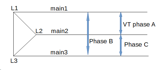
Three-phase delta is fairly rare, so isn’t covered in the documentation. I’m glad you were able to find that older post where we first worked out how to do it. In retrospect, it can be pretty simple, but first we need to establish the terminology that we are going to use. Let’s reprise the essential diagram in that post.
Here we have several different entities:
L1, L2 and L3 are the three mains cables also called main1, main2 and main3 respectively. So L1 is main1, L2 is main2, L3 is main3. From here on out, I’ll just refer to the three mains as L1, L2 and L3.
Phase A is a circuit connected between L1 and L2.
Phase C is a circuit connected between L2 and L3
Phase B is a circuit connected between L3 and L1
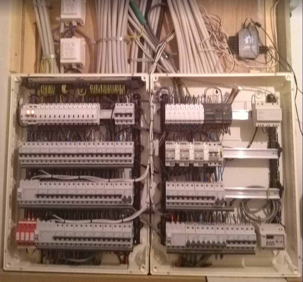
If you look at your service equipment, you should be able to identify the three distinct phases. The units that I have seen group the breakers for each phase together.
So when you say
We are really talking about the power of the circuit between two of the mains. So the power of phase A is the power used by a load connected to L1 and L2. Phase B is a load between L3 and L1. Phase C is a load between L2 and L3.
The current that flows in any of those three “phases” is not the same as the current that flows through the main1, main2 and main3 cables. The current through L1 (main1) is the algebraic sum of the phase A circuits and the phase B circuits. So measuring total power in your case is different from measuring the power used in the individual circuits.
That post explains how to measure total power with two CTs on the mains cables, essentially treating the third as a neutral. You should do that to get your total power as explained later.
The fact that it produces negative power notwithstanding, the inverter is just a load on one of the phases. If it is connected say between L1 and L3, it is on phase B. Simple as that.
So now to put this to practical use, you will be using “derived reference”. Your VT is installed on phase A, by definition. Any device connected to that phase should read the correct power. Identify the two mains that serve that phase. These are L1 and L2, although you don’t know yet which is which.
The other main is L3. Identify a significant load that is connected to L3 (either of the other two phases). Configure it’s CT as phase B. Cycle that load and watch the power change. Configure it as phase C and do that again. Whichever phase assignment causes the higher power value is the correct assignment. If it’s phase B the other main it is connected to is L1, if it’s phase C the other is L2. By elimination you now know all three L1, L2 and L3 and you know the CB bank that is Phase A, phase B and phase C.
The only thing left is to connect CTs to two of the mains to get total power. There are several ways to do it as explained in that old post. One way is to put CTs on L1 and L2, and configure them as phase C and phase B respectively. Total power is the sum of the two. You should “allow negative values” and you may need to experiment with “reverse” to get the correct result.
I’ll check back in on you when you have had a chance to digest this.
UPDATE: This post assumes you wanted to use only one VT with “derived reference”. IoTaWatt can also do all of this using “direct reference” and three VTs. To do so you would connect the two additional VTs to phases B and C and configure them on channels 13 and 14. You would then set the voltage reference of all the phase B and phase C CTs to the appropriate VT and set the phase to A on all CTs.
Thanks @overeasy for the thorough explanation.
I know exactly where L1,L2 and L3 and so where phase A, B and C are. And to keep it simple, I have the voltage input on phase A.
I already had the total power calculation up and running. And verified it by putting the same load on all 3 phases, one by one, and check if the power on all phases shows the same.
One strange thing in the setup I find, is that all the CT are connected in the same way (source/load) and still I had to reverse L1 to get the correct readings on the total power.
Is there any explanation on that?
The thing I was struggling with, was to get the individual power of the phases. Can you explain how to do that.
FYI: If needed I can also make use of direct reference (currently not yet connected).
Probably, but I don’t have the background to present a good analytic description. As a programmer, I do most of this empirically, as you have done with your proof.
Add up the power of all of the circuits on that phase. Phase A is L1-L2, so if you measure all of the circuits on phase A and add them up, that will be the total power for phase A. There are other possibilities, but I would need to see your distribution system to elaborate.
I suspect that you are really asking how to get the individual power of each of the mains cables L1, L2 and L3. I question the usefulness of that as each of the mains is connected to the other two, with different relative voltage, so arriving at Watts using just the one CT isn’t possible without a single voltage reference. A more useful metric might be Amps, which you can plot with Graph+ or create an output to display. You would need to put a CT on the third main to get it’s value.
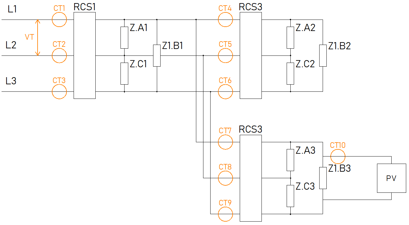
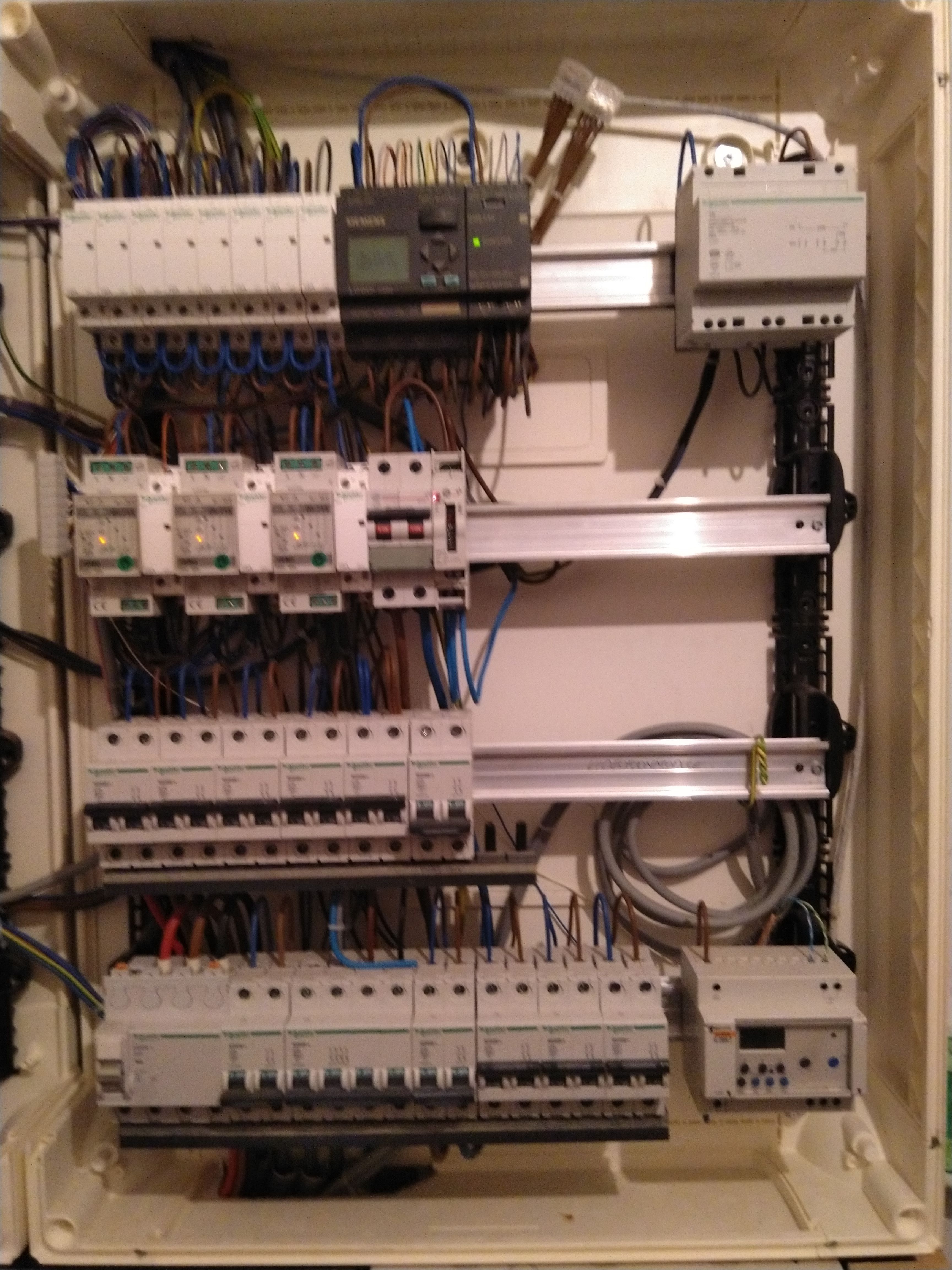
Here you see 3 residual current switches RCS1, RCS2 and RCS3. On the source side I can easily put CT’s so that is what I did. CT1 - CT9. CT10 is put on the inverter of the solar panels (with the source side to the PV’s).
With this setup the power going in to my total system would be the power through RCS1 (CT1,CT2,CT3) minus power of the PV (CT10).
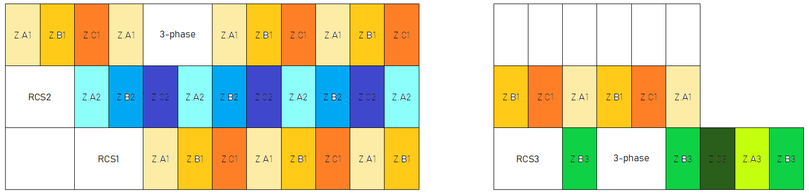
My idea was to measure the power of all of the Z.XX loads. 9 in total.
The power of Z.x2 should be easy to measure (I though). Same for Z.x3, if you forget about the PV.
The power of Z.x1 can be calculate with Z.xTotal - (Z.x2 + Z.x3).
So my question is how to measure for example the power of Z.A2, Z.B2 and Z.C2 in this setup?
I can’t respond to this today as I’m otherwise occupied, but in the meantime, could you edit your post with a better resolution photo with the cables in focus please? Also,if you could label the various RCS devices in the photo, and any of the groups like Z.A2 etc. would help.
Where you have placed the CTs in the line drawing, it’s not possible to do what you are asking. I can show where to put them on the line drawing, but a better picture might help determine if that’s possible without altering your wiring.
Also, can you post your IotaWatt inputs setup so I can see the phase assignments?
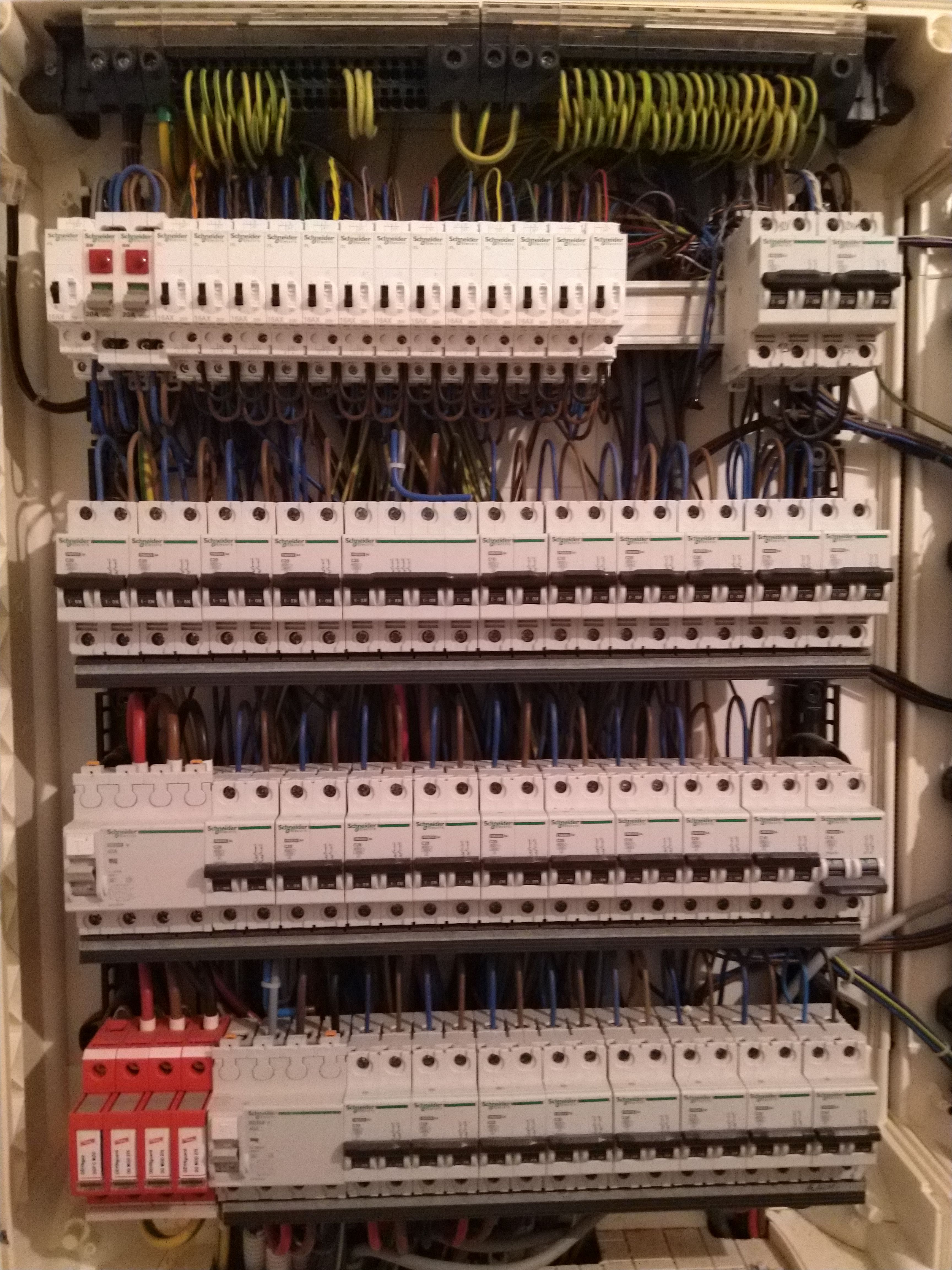
As you can see the bottom is connected with special copper bars. That way, every load circuit is evenly distributed over the 3 phases.
All the other row have a similar connection.
I made an overview of all the circuits and how they are distributed over the RCS’s and phases.
The bad news is that IoTaWatt can’t break down the individual A,B,C phase power. If the three CTs could be mounted on a common feed of those phases, you can do it, but the way the service is setup with the alternating buss, that isn’t possible. Each buss feeds two of the phases.
The good news is that you can measure the total used by each of the RCS1, RCS2 and RCS3 with just two CTs. So as you said previously, you can get total power (RCS1), RCS2, RCS3, and the power to the Z.x1 CTs as RCS1 - RCS2 - RCS3
The solar is single phase so you can measure that with 1 CT.
That uses 7 inputs. You can then measure 7+ additional inputs. A useful strategy might be to use those inputs to measure your largest or most interesting loads, and then subtract their power from their RCS group to get the residual power used by everything else in that group.
I also see that there are two three-phase loads. Those can also be measured with two CTs in the same way the RCS is measured.
Multiple circuits on the same phase can be measured using multiple 50A CTs and a headphone splitter to combine them into one input. The limitation is that the combined inputs cannot exceed 50A.
That’s the best I can do with the current IoTaWatt firmware. I did some poking around and found an instrument that can sort out the phase power using essentially three CTs on the mains. I found a used model for about $5,000. I don’t know how they do it, but it suggests it can be done with three power meters. There is no demand for this within the IoTaWatt community, but if someone points me to a description of the technique used to do this, I will consider adding it to the firmware, if possible.
I was already afraid it couldn’t be done.
The proposal you did with the 7 other dedicated inputs I already investigated, even before I came up with my current setup. But that didn’t give me enough information.
But for now I think we can leave this.