Share with group my New US Install

John,

My box from Lowes look like this (https://www.lowes.com/pd/CARLON-8-x-8-x-4-Junction-Box/3260229) and as you can see from the description it is 8x8x4 internal and there is some space to spare with the unit mounted. For some reason the one they show says non “longer available” and the one in the image has 4 screws where mine has 8 (3 top, 3 bottom, and one each side). Mine also does not have the small feet, is is just a box shape. I like the second option from Amazon you show, as that has a door and closure. You will be making modification or slight tweaks so I left mine open (due to screws) until all was done. If you have the time and can spend a bit more, I would go with the Amazon second one if I had to do it again.

I agree that the best location for your IoTaWatt box is where the timer box is currently placed. If you are able to move it and put a box there I think you would have a winner. Electricians are only thinking of themselves when they install these panels :). I would use something like 1.5" conduit based on the number of runs you expect, or 1" if you plan on distributing them between panels. Mine is 1" and it is tight with 12 CT cables but I plan on snaking through the others in the near future.

If there are 1" punchouts at the bottom of the panels, that would give you the most room for the drops. Just not sure what you have below. The sub seems to have bottom punches it was done during install. I think it would be difficult to use the main as a pass-through in this configuration. It may be good for an electrician to do the conduit work if you have to do any drilling as you said. I know there is a cost, but this is your house you are speaking about.

1 Like

It has been a while, and I’m not “done” yet (ha ha, maybe we never are), but its all installed and working pretty well. Some of you might be interested to see this - USA split phase 240V setup. Still somewhat of a tangle of CT wires, splitters,etc. There are 22 CTs in there, combined via splitters, a couple left for summer/winter changeover (AC compressors in summer, roof snow melt in winter), some where multiple circuits go through 1 CT, some doubled on one leg of 240V circuit.

I chose not to enclose the CT wires in conduit; just no way to make that all work, and couldn’t really see the point. I may try to cover with smurf tubing or similar, later. I just ran them through panel knockouts in plastic cable clamps, with the clamp cut out and smoothed inside. Tied them all neatly inside the panel, then looped outside.

The Extreme Broadband enclosure shown in the thread above worked pretty well. The iotawatt mounting clip screwed nicely to the tracks inside, so iotawatt can easily be unclipped and pulled partly out for access, then clipped back. The many cable slots with foam retainers were great to keep the cables under control, and still easily moveable. Not tons of extra room inside once I started with the 2, 3, and 4 way splitters! But it all fits. Door has a clip, and a lock option - I don’t need to lock mine.

Thanks to so many in the community for good ideas posted along the way, and especially to Bob for the great product and all the ongoing hard work on continued support and tips and hints!


John

1 Like

Awesome to see and know that you are up and running. And, yes, we are never done. There are always little tweaks and tunes as you said; and season changes help that also.

Wow, I though I had quite a bit with mine, but with your sub panel, etc, it looks very nice. You can always clean up those CT wires another day; or not. :slight_smile:

I would have gone the conduit route myself for the CT wires, but that is more for form than function. Again, you can clean them up later of you desire. I like the run between the sub-panel and the main panel for the CTs. It looks professional and clean. Good job!

I agree that it looks quite nice and I like that you have the option with a latch and lock if ever needed. When it is all closed up, it gives you access to the box quickly of you should need. The junction box I used in my install requires eight screws to come off. However, once all is working, I do not plan on taking it out.

Thanks can not be said enough for this group and Bob for all the help, direction, pointers, and feedback. I’m sure Bob does not sleep ever as he is aways on the board answering questions and willing to assist at any time. Very nice install, thanks for sharing it.

Thank you for taking the time to share your install photos and links to some of the accessories you used. I have been contemplating how to install my IoTaWatt for a month now. :slight_smile: I have two panels as well, however one is on the outside of the house (Main Panel with all 220VAC breakers) and the other is in my garage (Sub Panel, mostly 110VAC breakers). Unfortunately, my two panels are about 60 feet apart from one another, so it may be simpler to just buy another IoTaWatt, since I need significantly more than 14 CTs anyway.

My garage mounted panel is flush-mounted in the sheet-rock, so I am going to need to perform some cutting and add some conduit.

Again, thanks for the write-up and the pictures. Seeing your installation helps me to visualize mine.

I have to say that’s a pretty amazing instrumentation effort. It may look easy to anyone whose not tried it, but getting that number of CTs in a panel as neatly as that is very hard to do. It would not be possible with YHDC SCT013-000 CTs as they are much larger and the cables are too short.

But enough about the visuals. How is the data working out?

Great to see some interest in this! I’ll try to answer; let me know if there is or should be a better thread for these topics.

@quella: there is no CT run from sub to main panel. There is one place it almost looks like that, but only the subpanel power feed from main goes between. The CT runs exit the subpanel at top, run across the top of the main, behind the vertical HV wiring, then down between main and iotawatt box to enter in bottom. Any other way, CT wires were too short. All the larger knockouts in panels I’d use for conduit resulted in CT wires too short, or too much interference.

@ogiewon: you will probably need 2 iotawatts, and have to open up your drywall but you may also want to consider using low voltage wiring techniques, smurf tubes and such. Easy for me as my area is open and can stay that way and I’m more concerned about being safe and reasonable than trying to meet current code. Just don’t think that you will need 1 iotawatt channel per CT or per circuit. (see below)

@overeasy: The data is great, and is coming together in a way that makes sense to me in my situation. Has taken quite a while to work out, connect and map things, look at what I’m tracking, create outputs, then rethink and redo things, move CTs, group different ways. I don’t know if there is a generic method, “how to approach it” FAQ or something like that. I started out like @ogiewon sounds - get iotawatt US kit and set of CTs, hook up bunch of circuits 1 to 1, targeting heavy consumers, with panels open, CT cables dangling, run it, see how it looks in real time. Did not think much in advance about exactly what I WANTED to see, I’d recommend doing that though :slight_smile:

My environment - single house, not all-electric, no solar, using 25-30 kWh/day. (500-700W at night). Complex HVAC with 3 zones, separate circuits for AC compressors, air handlers, oil fired boiler (also heats hot water), ductless mini-split - already 8 to monitor! And also electric range, washer, dryer, dishwasher, refrigerator, microwave, espresso machine, 3-4 areas with PCs, TVs, etc, some use 2 or more circuits. Also 2 circuits for ice melting roof heat wires. Many small devices everywhere that have constant small draw.

Easy to assign the mains, with a 200A CT on each phase, and an output to sum them, but then what? Just looking at the heavy users and all the HVAC units is interesting, but only covers a small % of the total kWh as they only run occasionally, and already consume all the iotawatt channels.

So to jump ahead, I wanted decent granular visibility into a majority of the daily uses, and which HVAC zones were active, while fitting into the 12 remaining channels somehow. I ended up making 2 spreadsheet table/maps: one is the set of 14 iotawatt channels with the CT or CTs that feed each and a few notes (and yes, I’d STRONGLY recommend labeling each end of every CT cable, I used a Klein label pack. $10 and worth it!). The other is the set of circuits I’m monitoring with their panel location, phase, CT # used, iotawatt channel, notes. I’d actually recommend first making a list of what YOU want to monitor, independent of exact circuits, CTs, channels, as you may combine circuits, CT outputs, and channels in interesting ways for yourself. Simplest example, I mostly do not care to see split phase A and B, just want to see total power.

I can share more of the maps if there is interest, not sure of best way to do that. Here’s what I ended up with:

image

I used @overeasy’s suggestion to create an “unmeasured” output: mains minus all other channels, very useful.

I got some 2, 3 and 4 way headphone splitters to combine CT outputs. I ran 2 circuits through a couple CTs where that was possible and meaningful. I consciously evaluated some circuits and relegated them to the unmeasured category, so I know about 100-300 W in that virtual bucket. I combined the 3 AC compressor circuits using 2 CTs, double wired one, them merge with a splitter, but not using a channel until next summer. Combined washer CT with roof heaters, (2 in 1 CT), for winter. Combined 4 kitchen circuits/CTs into 1 channel with splitter, similar with living room, family room, bedroom areas, then those into the Live_Work output. Of course combining circuits reduces granular visibility, but I already understood what some of the components looked like - fridge is steady mostly-on 150W, microwave is short 1500W bursts, espresso is 1000W steady heatup then bursts as boiler cycles or make a cup. You can see this below.

Here’s one snapshot sample for today’s use, and now this posting is long enough! Can discuss and post more later if interest.

Note: I also set up emoncms on an RPI to feed iotawatt data for historical, also try to figure out how to log fuel oil consumption based on boiler burner on-time and G/hr rating of burner nozzle.

John

1 Like

Thanks for sharing your experience. Nice project.

I have been doing this for years with a Hobo datalogger. It uses a magnetic switch so I just stick it on the burner motor and it records when the motor runs. Your burner nozzle rating is dependent on age and pump pressure. To calibrate, record the burner time between fills and compute the actual rate. You can accumulate the data starting now and retroactively calibrate.

1 Like

Might have to go that way. If I did, I could free up that channel, combine into another HVAC-related channel. Still nice to see when burner runs for heat vs. hot water. Need more conditional test capability to really do that automatically.

Figured burner has own channel, draws 250W when running, almost nothing when idle, so I have emoncms (on RPI) process that “should” count time when draw is over 100W, and then math to convert run time into gallons, but can’t see how to accumulate those gallons over time like kWh are accumulated, and the ontime function does not do what I thought it did, help info is hard to find, the programing process is very quirky and limited, I always have to remember how the UI works, how the inputs, feeds, virtual feeds all tie together or not. Might reach out on that community, or give up :slight_smile:

1 Like

You may be able to work some of the math out using virtual feeds based off the inputs, etc. I have also been interested in the measuring of out fuel oil tank amounts, and have seen a few people that have built out a few ESP8266 modules with ultrasonic sensors mounted in the top of the tank (via some of the plugged holes. They use this to measure the liquid depth and based on how far it is from the sensor translates to the amount of fuel you have in the tank.

As you said, for measuring flow usage, you could take the data sheet from the burner you have and translate usage based on some estimates of flow from the manufacturer. I was looking more for a way to keep track of the amount rather then flow.

I was looking at something like this:

or this:

Here are some pictures of my IoTaWatt installation. This is a Sub-Panel in my garage, which has mainly 120VAC loads. The 240VAC circuits are primarily handled in the outside Main-Panel (will need a second IoTaWatt for that panel :wink: )

Sub-Panel

Inside

I used an Orbit Sprinkler enclosure, as it is the perfect size, has room for cable management under the main surface, and has a built-in GFCI Outlet. I had to add a 15 Amp breaker to my panel to feed this enclosure with power for the IoTaWatt.

I used 1" smurf tube for the CT cables. It was snug, but all 14 cables fit.

Here is what the inside of the finished panel looks like.

And the wall with everything buttoned back up.

Thank you to everyone else who has shared their installation experiences. I got lots of great ideas from all of you!

2 Likes

Nice score on that enclosure. At first it looked pricey, but I didn’t realize it had the GFI duplex outlet. Very clean install, nice job.

1 Like

Yes, it is a little pricey, but it really works very well, and is designed to be used outdoors as a waterproof sprinkler controller enclosure. So, when I install the next IoTaWatt at the Main Panel, I know I’ll have a working solution. I’ll just need to figure out how to do the conduit between the two boxes. Unfortunately, the Main Panel is completely full of 6 x 240VAC breakers. So, I am not sure where I will be getting the 110VAC needed for the IoTaWatt’s adapters.

Check with an electrician, but I think it’s copacetic to use one leg of a 240 breaker along with neutral if you have a 20A or less 240 breaker.

1 Like

Very nice and clean install, thanks for sharing. I like the conduit run as I would have thought the surface mounted box would have been hard to make connection. Wires are labeled and the ties keep is very professional looking. It looks great.

1 Like


Orbit sprinkler box installed. Two outlets for each Vt to plug into. Iotawatt should be here tues.

2 Likes

Looks good. it will look even better once the IoTaWatt is in and running. :slight_smile:

1 Like

Ahhh Much better now. It was missing something earlier. :slight_smile:

1 Like

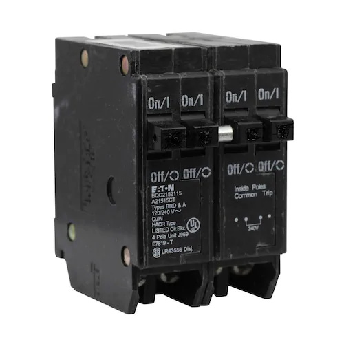
So, I finally finished the installation of my second IotaWatt on my outdoor Main Panel. My solution to the lack of 120vac was solved by using a 240VAC “Tandem Breaker”, which turns a standard 30A 240VAC breaker into 1- 30A 240VAC + 2-15A 120VAC breakers. This allowed me to safely add a 15A circuit just for the Orbit Sprinkler Enclosure’s GFCI outlet.

image

The hardest part was getting the 12 CT wires through the 3/4" conduit. I really should have ordered some 1" conduit…but I simply grabbed what Home Depot had in stock (1/2" for the 120VAC power + 3/4" for the CT wiring.)

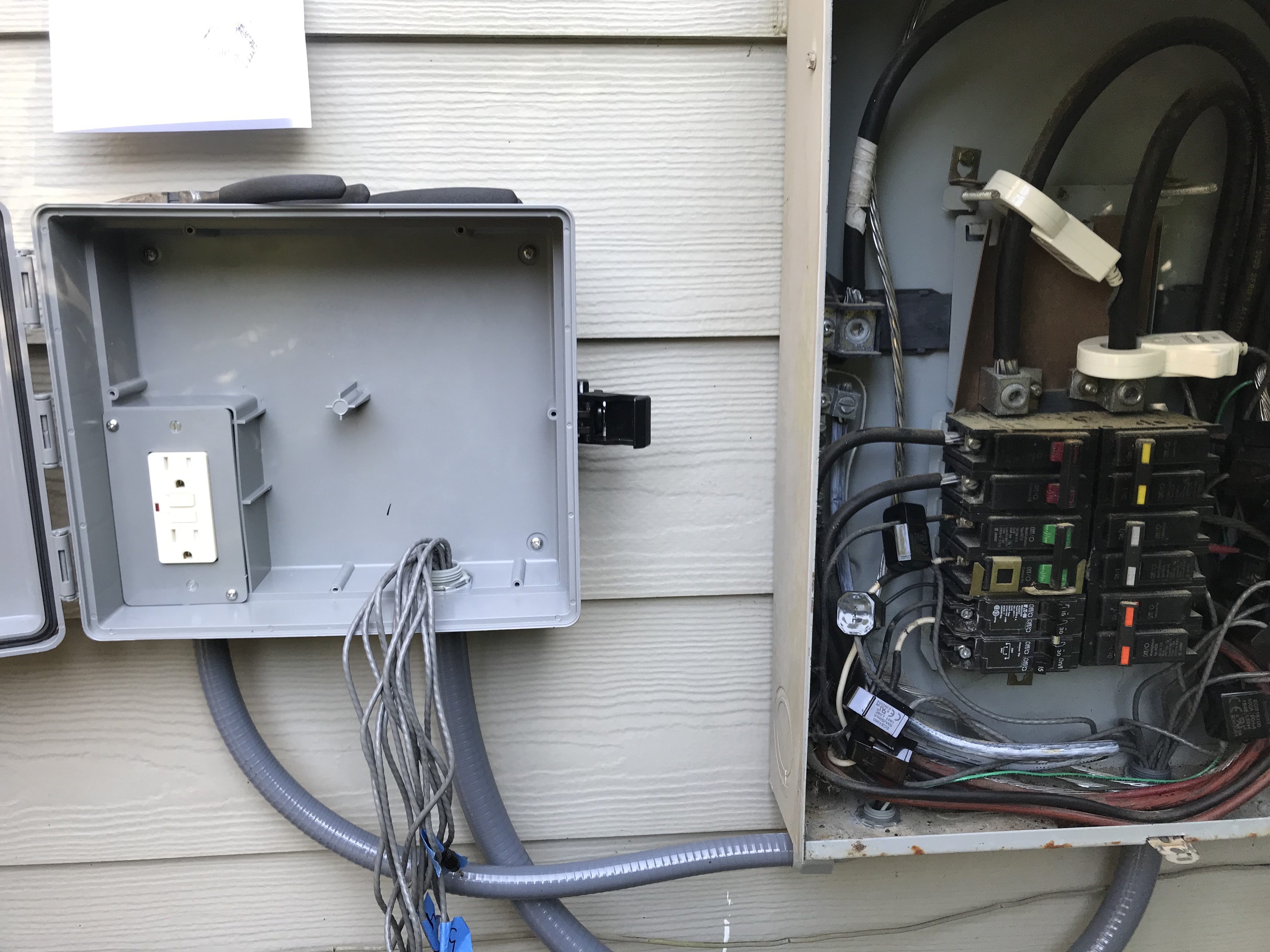
All finished and working great!

Note: I did have one issue with the GFCI Orbit Sprinkler enclosure’s outlet. This newer enclosure came with a useless GFCI outlet. If I plugged anything into the top outlet, power was killed to both outlets. I took the outlet apart to find a very poorly designed electro-mechanical outlet. I tossed it into the trash and bought a 15A Leviton GFCI at Home Depot. Problem solved.

Now I have a complete view of electricity usage within my home. All data is being collected by InfluxDB on a local Windows 10 machine, which also hosts Grafana.

3 Likes

Looks great. Now sit back and enjoy the data you get from it. A wonderful tool!

2 Likes